
2 Note


Using Voltage Identifier (VID) Signals
14 307507-002
4 Using Voltage Identifier (VID)
Signals
VCCP and VTT are used to power the test chip. The test chip does not provide control
on the VID signals to establish a VCCP voltage when plugged into a socket. A VID
signal combination should be connected to ground and controlled by the test
equipment in such a way that an on-board VCCP is generated that equals the on-
board VTT voltage.
To determine which VID lines to use in order to keep VCCP equal to VTT, refer to the
Voltage Regulator Down (VRD) Design Guide for the processor being used (section
1.2
of this document).
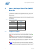
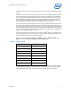
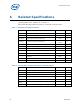
Table 4 - Voltage Identifier Signals
Signal Name VID Ball
VID_0
AM2
VID_1
AL5
VID_2
AM3
VID_3
AL6
VID_4
AK4
VID_5
AL4
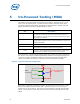
4.1 Using Control Signals
To ensure that the switches default to OFF when power is applied or while other
devices are being tested, the control signals are pulled to ground with 1KOHM
resistors. Each control signal can turn a grouping of approximately 64 switches ON
and OFF.
Each ON/OFF switch pair tests three socket solder balls and socket contacts, not
including the control signals. A logic level high on the control signal will turn its
associated switch to the ON state.
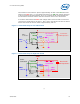
Four pairs of Hcontrol and Lcontrol inputs are used to multiplex the signals that are
received by the test equipment across more than one switch pair in order to test the
majority of power and ground electrical socket connections.
Caution: At no time should the control signal for the High Side and Low Side
switches be driven high at the same time, as can occur with some automated fault
injection tools. A direct short from power to ground would result and possibly damage
the Intel
®
Socket Test Technology test chip and the board under test. To prevent