
2 Note


Introduction
4 307507-002
Figures
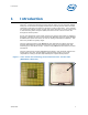
Figure 1 - Intel
®
Socket Test Technology for the LGA775 Socket - Product Code
JM8YKZLVA (LGA775YP).......................................................................................................
7
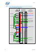
Figure 2 - Intel
®
Socket Test Technology for the LGA775 Socket - Block Diagram
Product Code JM8YKZLVA (LGA775YP)............................................................................
10
Figure 3 - Typical Switch Pair Configuration...........................................................................18
Figure 4 - Instrument Setup for Low Side Switch.................................................................19
Figure 5 - Instrument Setup for High Side Switch................................................................19
Figure 6 - Optimized Ball Coverage Map.................................................................................35
Tables
Table 1 - Voltage Identifier Signals..........................................................................................11
Table 2 - Control Signals............................................................................................................12
Table 3 - Test Head Loads..........................................................................................................13
Table 4 - Voltage Identifier Signals..........................................................................................14
Table 5 - Control Signals............................................................................................................15
Table 6 - Test Head Loads..........................................................................................................16
Table 7 - Electrical Operating Parameters ..............................................................................20
Table 8 - Test Condition for High Side Switch (Powered Digital).......................................20
Table 9 - Test Condition for Low Side Switch (Powered Digital)........................................21
Table 10 - Test Condition for Switch (Un-powered Analog)................................................21
Table 11 - Balls Used as Control Signals.................................................................................22
Table 12 - Ball Groupings/Functions........................................................................................22
Table 13 - Zero ohm Resistor....................................................................................................31
Table 14 - 1 kohm Measurements............................................................................................32
Table 15 - 1 kohm Measurements............................................................................................32
Table 16 - 1 kohm Measurements............................................................................................33
Table 17 - Package Resistive Measurements..........................................................................34