
2 Note


Un-Powered Testing (MDA)
18 307507-002
5 Un-Powered Testing (MDA)
The following test method was developed using an Agilent* 3070 Series II In-circuit
tester in an un-powered mode. The technique and results should be similar when
using test equipment with similar capabilities as described below. (Please note that
Agilent was formerly known as Hewlett Packard* or HP).
Bus Description
S Bus Primary Source. Provides -10.0 V to +10.0 V (VDC) by connecting
the high side to the Device under Test (DUT) through a 500-ohm
series resistance. The low side connects itself automatically to digital
and switched analog GND.
A Bus Auxiliary Source. Provides -10.0 V to +10.0 V (VDC) by connecting
the high side to the DUT and the low side automatically to digital and
switched analog GND.
I Bus The high side of a DC voltmeter connected to the DUT.
L Bus The low side of a DC voltmeter connected to digital and switched
analog GND unless otherwise specified through software.
G Bus Guard Bus. Used to break parallel impedance paths. In this case, it
connects VCCP and GND to keep them at the same potential.
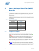
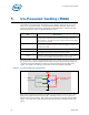
The typical Intel
®
Socket Test Technology switch pair is shown in Figure 3 using the G
Bus to short circuit VCCP to GND and potentially eliminates the charge/discharge time
caused by the large capacitance present on the board when testing the High Side
switch. The intent is to make the overall test as fast and reliable as possible.
Figure 3 - Typical Switch Pair Configuration
GND
VCCP
Signal
Board VCCP- GND
Capacitance
Hcontrol
Lcontrol
G Bus
Connection
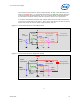
Each switch is tested by connecting the A Bus to the Hcontrol or Lcontrol, the S and I
Buses to the Signal, and the L Bus to GND. The A Bus is set to 1.2 V to ensure a
positive turn on of the switch. The S Bus is set to 600 mV for the High and Low Side
switch. The S Bus uses a 500 ohm series resistance for both the High and Low Side
switch.