
Intel Celeron Processor in the 478-Pin Package at 1.80 GHz Datasheet

92 Datasheet
Intel
®
Celeron
®
Processor in the 478-Pin Package
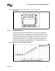
The target load applied by the clips to the processor heat spreader for Intel’s reference design is
75 ± 15 lbf (maximum load is constrained by the package load capability). It is normal to observe a
bow or bend in the board due to this compressive load on the processor package and socket. The
level of bow or bend depends on the motherboard material properties and component layout. Any
additional board stiffening devices (such as plates) are not necessary and should not be used with
the reference mechanical components and boxed processor. Using such devices increases the
compressive load on the processor package and socket, likely beyond the maximum load that is
specified for those components. See the Intel
®
Pentium
®
Processor in the 478 pin Package
Thermal Design Guidelines for details on the Intel reference design.
Chassis that have adequate clearance between the motherboard and chassis wall (minimum 0.250
inch) should be selected to ensure that the board’s underside bend does not contact the chassis.
8.2 Electrical Requirements
8.2.1 Fan Heatsink Power Supply
The boxed processor's fan heatsink requires a +12 V power supply. A fan power cable will be
shipped with the boxed processor to draw power from a power header on the motherboard. The
power cable connector and pinout are shown in Figure 36. Motherboards must provide a matched
power header to support the boxed processor. Table 37 contains specifications for the input and
output signals at the fan heatsink connector. The fan heatsink outputs a SENSE signal, which is an
open-collector output that pulses at a rate of two pulses per fan revolution. A motherboard pull-up
resistor provides V
OH
to match the system board-mounted fan speed monitor requirements, if
applicable. Use of the SENSE signal is optional. If the SENSE signal is not used, pin 3 of the
connector should be tied to GND.
Note: The motherboard must supply a constantat +12V to the processor’s power header to ensure proper
operation of the variable speed fan for the boxed processor.
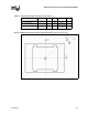
The power header on the baseboard must be positioned to allow the fan heatsink power cable to
reach it. The power header identification and location should be documented in the platform
documentation, or on the system board itself. Figure 37 shows the location of the fan power
connector relative to the processor socket. The motherboard power header should be positioned
within 4.33 inches from the center of the processor socket.
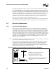
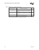
Figure 36. Boxed Processor Fan Heatsink Power Cable Connector Description
Pin Signal
Straight square pin, 3-pin terminal housing with
polarizing ribs and friction locking ramp.
0.100" pin pitch, 0.025" square pin width.
Waldom/Molex P/N 22-01-3037 or equivalent.
Match with straight pin, friction lock header on motherboard
Waldom/Molex P/N 22-23-2031, AMP P/N 640456-3,
or equivalent.
1
2
3
GND
+12 V
SENSE
123