
Intel Celeron Processor on 0.13 Micron Process in the 478-Pin Package Datasheet

Intel
®
Celeron
®
Processor on 0.13 Micron Process in the 478-Pin Package Datasheet 27
Electrical Specifications
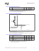
NOTES:
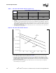
1. See Table 13 for range of RON.
2. The VCC referred to in this figure is the instantaneous VCC.
3. Refer to the ITP700 Debug Port Design Guide and the Platform Design Guide for the value of Rext.
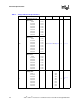
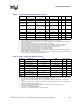
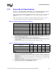
Table 13. ITPCLKOUT[1:0] DC Specifications
Symbol Parameter Min Max Unit Notes
1
NOTES:
1. Unless otherwise noted, all specifications in this table apply to all processor frequencies.
Ron Buffer On Resistance 27 46 Ω
2,
3
2. These parameters are not tested and are based on design simulations.
3. See Figure 5 for ITPCLKOUT[1:0] output buffer diagram.
Figure 5. ITPCLKOUT[1:0] Output Buffer Diagram
RON
VCC
Processor Package
RTEXT
To Debug Port
ITPCLKOUT Buff
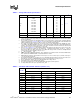
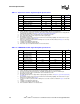
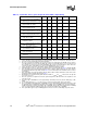
Table 14. BSEL [1:0] and VID[4:0] DC Specifications
Symbol Parameter Min Max Unit Notes
1
NOTES:
1. Unless otherwise noted, all specifications in this table apply to all processor frequencies.
Ron (BSEL) Buffer On Resistance 9.2 14.3 Ω
2
2. These parameters are not tested and are based on design simulations.
Ron (VID) Buffer On Resistance 7.8 12.8 Ω
2
I
HI
Pin Leakage Hi N/A 100 µA
3
3. Leakage to VSS with pin held at 2.50 V.