
Intel Celeron Processor in the 478-Pin Package at 1.80 GHz Datasheet

52 Datasheet
Intel
®
Celeron
®
Processor in the 478-Pin Package
NOTES:
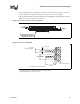
1. Flatness is specific as overall, not per unit of length.
2. All dimensions are in mm.
4.1 Package Load Specifications
Table 27 provides dynamic and static load specifications for the Celeron
processor in the 478-pin
package IHS. These mechanical load limits should not be exceeded during heatsink assembly,
mechanical stress testing, or standard drop and shipping conditions. The heatsink attach solutions
must not induce continuous stress onto the processor with the exception of a uniform load to
maintain the heat sink-to-processor thermal interface. It is not recommended to use any portion of
the processor interposer as a mechanical reference or load bearing surface for thermal solutions.
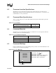
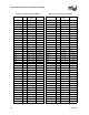
NOTES:
1. This specification applies to a uniform compressive load.
2. This is the maximum static force that can be applied by the heatsink and clip to maintain the heatsink and
processor interface.
3. These parameters are based on limited testing for design characterization.
4. Dynamic loading specifications are defined assuming a maximum duration of 11ms and 200 lbf is achieved
by superimposing a 100 lbf dynamic load (1 lbm heatsink at 50 g) on the static compressive load.
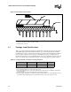
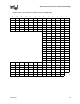
Figure 26. IHS Flatness Specification
SUBSTRATE
IHS
SUBSTRATE
IHSIHS
Table 27. Package Dynamic and Static Load Specifications
Parameter Max Unit Notes
Static 100 lbf 1, 2, 3
Dynamic 200 lbf 1, 3, 4