
Guide

Intel
®
Celeron
®
D Processor for Embedded Applications Thermal Design Guide 9
Design Guidelines
2.0 Design Guidelines
The thermal solutions presented in this document are designed to fit within the maximum
component height allowed by certain embedded form factor specifications, including ATX, 2U,
and 1U server form factors. The thermal solutions may be valid for other form factors; however,
individual applications must be modeled, prototyped, and verified.
In some cases, prototype parts have been fabricated for verification tests.
Note: The thermal verification information described in this document is not adequate for statistical
purposes. The intent of testing was only to verify that the thermal components were performing
within reasonable expectations, based on computer modeling and component specifications.
2.1 Mechanical Guidelines
2.1.1 Processor Package
The Intel
®
Celeron
®
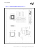
D Processor for Embedded Applications is packaged in a Flip-Chip Pin Grid
Array (FC-mPGA4) package technology. Refer to the processor datasheet for detailed mechanical
specifications of the FC-mPGA4 package. For reference, the FC-mPGA4 package is shown in
Figure 1 and Figure 2.
The package includes an Integrated Heat Spreader (IHS). The IHS spreads non-uniform heat from
the die to the top of the IHS, out of which the heat flux is more uniform and on a larger surface
area. This allows more efficient heat transfer out of the package to an attached cooling device.
It is incorrect to assume that processor power is dissipated uniformly on the IHS. In particular,
when validating a thermal solution, an Intel Celeron D Processor Thermal Test Vehicle (TTV) shall
be used and a correlation to real parts applied to the results.
The IHS is designed to be the interface for mounting a heatsink. Further details are found in the
processor datasheet.
The processor connects to the motherboard through a ZIF surface-mount socket. The socket is
described in the Intel
®
Pentium
®
4 Processor, 478-Pin Socket (mPGA478B) Design Guidelines.
To facilitate customer assembly and ensure proper alignment and cooling performance, the
heatsink base must be designed for symmetrical assembly. Refer to Section 2.1.3.3, “Additional
Requirements for Solutions Using Reference ATX Heatsink and Reference Clip” on page 19 for
further information on the interface to the motherboard.
It is not recommended to use any portion of the interposer as a mechanical reference or
load-bearing surface in either static or dynamic compressive load conditions.