
Intel Celeron Processor for the PGA370 Socket up to 1.40 GHz on 0.13 Micron Process Datasheet

30 Datasheet
Intel
®
Celeron
®
Processor for PGA370 up to 1.40 GHz on 0.13 µ Process
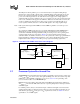
2.12 AGTL System Bus Specifications
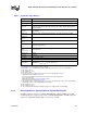
It is recommended that the AGTL bus be routed in a daisy-chain fashion with termination resistors
to V
TT. These termination resistors are placed electrically between the ends of the signal traces and
the V
TT voltage supply. The valid high and low levels are determined by the input buffers using a
reference voltage called V
REF
. Refer to the appropriate platform design guide for more information
Table 13 lists the nominal specification for the AGTL termination voltage (V
TT). The AGTL
reference voltage (V
REF
) is generated on the system motherboard and should be set to 2/3 VTT for
the processor and other AGTL logic. It is important that the baseboard impedance be specified and
held to a ±15% tolerance, and that the intrinsic trace capacitance for the AGTL signal group traces
is known and well-controlled. For more details on the AGTL buffer specification, see the
Intel
®
Pentium
®
II Processor Developer's Manual and AP-585, Intel
®
Pentium
®
II Processor
AGTL Guidelines.
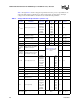
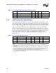
NOTES:
1. Unless otherwise noted, all specifications in this table apply to the processor up to 1.40 GHz frequency.
2. The processor for the PGA370 socket contain AGTL termination resistors on the processor die, except for the
RESET# input.
3. V
TT must be held to 1.25 V ±9%. It is required that VTT be held to 1.25 V ±3% while the processor system bus
is idle (static condition). This is measured at the PGA370 socket pins on the bottom side of the baseboard.
4. Uni-processor platforms require a 56
Ω resistor and dual-processor platforms require a 68Ω resistor.
Tolerance for on-die Rtt is ±10% (56
Ω, 68 Ω resistors). Rtt is ±15% (100 Ω resistors).
5. V
REF
is generated on the motherboard and should be 2/3 VTT ±5% nominally. Insure that there is adequate
V
REF
decoupling on the motherboard.
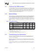
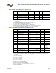
Table 12. 3.3 Volt CMOS Output Signal Group DC Specifications
Symbol Parameter Min Max Unit Notes
V Nominal Voltage 3.45 V 3.3 + 5%
V
OH Output High Voltage 0.9 V
I
LO Output Leakage Current 100 µA
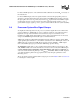
Table 13. Processor AGTL Bus Specifications
Symbol Parameter Min Typ Max Units Notes
1,2
VTT Bus Termination Voltage 1.1375 1.25 V 3
On-die R
TT
Termination Resistor 50
56
68
115
Ω 4
V
REF
Bus Reference Voltage 2/3VTT V5