
Intel Celeron Processor on 0.13 Micron Process in the 478-Pin Package Datasheet

Intel
®
Celeron
®
Processor on 0.13 Micron Process in the 478-Pin Package Datasheet 83
Thermal Specifications and Design Considerations
NOTES:
1. These values are specified at VCC_MAX for the processor. Systems must be designed to ensure that the
processor is not subjected to any static VCC and I
CC
combination wherein VCC exceeds V
CC
_MAX at
specified I
CC
. Refer to loadline specifications in Chapter 2.
2. The numbers in this column reflect Intel’s recommended design point and are not indicative of the maximum
power the processor can dissipate under worst case conditions. For more details refer to the
Intel
®
Pentium
£
4 Processor in the 478-pin Package Thermal Design Guidelines.
3. Also applies to processors with fixed VID=1.525 V.
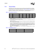
6.1.2 Thermal Metrology
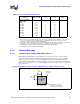
6.1.2.1 Processor Case Temperature Measurement
The maximum and minimum case temperature (T
C
) for the Celeron processor on 0.13 micron
process is specified in Table 37. This temperature specification is meant to ensure correct and
reliable operation of the processor. Figure 36 illustrates where Intel recommends T
C
thermal
measurements should be made. For detailed guidelines on temperature measurement methodology,
refer to the Intel
®
Pentium
®
Processor with 512-KB L2 Cache on 0.13 Micron Processor Thermal
Design Guidelines.
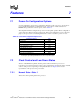
Table 37. Processor Thermal Design Power
Processor and Core
Frequency
Thermal Design
Power
1,2
(W)
Minimum TC
(°C)
Maximum TC
(°C)
Notes
For Processor with
multiple VIDs:
2 GHz
3
2.10 GHz
2.20 GHz
2.30 GHz
2.40 GHz
2.50 GHz
2.60 GHz
2.70 GHz
2.80 GHz
52.8
55.5
57.1
58.3
59.8
61.0
62.6
66.8
68.4
5
5
5
5
5
5
5
5
5
68
69
70
70
71
72
72
74
75
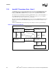
Figure 36. Guideline Locations for Case Temperature (T
C
) Thermocouple Placement
Measure From Edge of Processor
Measure T
at this point.
C
Thermal interface material
should cover the entire surface
of the Integrated Heat Spreader
0.689”
17.5 mm
0.689”
17.5 mm
35 mm x 35 mm Package