
Intel Celeron Processor for the PGA370 Socket up to 1.40 GHz on 0.13 Micron Process Datasheet

42 Datasheet
Intel
®
Celeron
®
Processor for PGA370 up to 1.40 GHz on 0.13 µ Process
3.2 AGTL Signal Quality Specifications and Measurement
Guidelines
Many scenarios have been simulated to generate a set of AGTL layout guidelines which are
available in the appropriate platform design guide. Refer to the Intel
®
Pentium
®
II Processor
Developer's Manual (Order Number 243502) for the AGTL buffer specification.
Table 25 provides the AGTL signal quality specifications for the processor for use in simulating
signal quality at the processor pins.
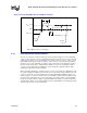
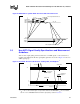
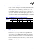
The processor maximum allowable overshoot and undershoot specifications for a given duration of
time are detailed in Table 24 through Table 26. Figure 19 shows the AGTL ringback tolerance and
Figure 20 shows the overshoot/undershoot waveform.
NOTES:
1. Unless otherwise noted, all specifications in this table apply to the processor up to 1.40 GHz frequency.
2. Specifications are for the edge rate of
0.3 – 3 V/ns. See Figure 19 for the generic waveform.
3. All values specified by design characterization.
4. See Table 24 for maximum allowable overshoot.
5. Ringback between V
REF
+ 100 mV and V
REF
+ 200 mV or V
REF
– 300 mV and V
REF
– 100 mVs requires the
flight time measurements to be adjusted as described in the Intel AGTL Specifications. Ringback below
V
REF
+ 100 mV or above V
REF
– 100 mV is not supported.
6. Intel recommends simulations not exceed a ringback value of V
REF
±200 mV to allow margin for other
sources of system noise.
7. A negative value for
ρ indicates that the amplitude of ringback is above V
REF
. (i.e., φ = -100 mV specifies the
signal cannot ringback below V
REF
+ 100 mV).
8.
φ and ρ: are measured relative to V
REF
. α: is measured relative to V
REF
+ 200 mV.
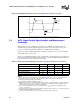
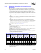
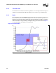
Figure 18. BCLK/BCLK#, PICCLK Generic Clock Waveform at the Processor Pins
V2
V1
V3
V3
V4
V5
Table 25. AGTL Signal Groups Ringback Tolerance Specifications at the Processor Pins
T# Parameter Min Unit Figure Notes
1,2,3
α: Overshoot 100 mV 19 4, 8
τ: Minimum Time at High 0.50 ns 19
ρ: Amplitude of Ringback ±200 mV 19 5, 6, 7, 8
φ: Final Settling Voltage 200 mV 19 8
δ: Duration of Squarewave Ringback N/A ns 19