
Intel Celeron Processor on 0.13 Micron Process in the 478-Pin Package Datasheet


90 Intel
®
Celeron
®
Processor on 0.13 Micron Process in the 478-Pin Package Datasheet
Features
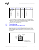
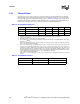
7.3.1 Thermal Diode
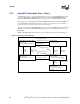
The Celeron processor on 0.13 micron process incorporates an on-die thermal diode. A thermal
sensor located on the system board may monitor the die temperature of the processor for thermal
management/long term die temperature change purposes. Table 39 and Table 40 provide the diode
parameter and interface specifications. This thermal diode is separate from the Thermal Monitor’s
thermal sensor and cannot be used to predict the behavior of the Thermal Monitor.
Table 39. Thermal Diode Parameters
Symbol Parameter Min Typ Max Unit Notes
1
NOTES:
1. Intel does not support or recommend operation of the thermal diode under reverse bias.
I
FW
Forward Bias Current 5 300 µA
1
n Diode Ideality Factor 1.0011 1.0021 1.0030
2,
3,
4
2. Characterized at 75 °C.
3. Not 100% tested. Specified by design characterization.
4. The ideality factor, n, represents the deviation from ideal diode behavior as exemplified by the diode equa-
tion:I
FW
=I
s
*(e
(qVD/nkT
-1)
Where I
S
= saturation current, q = electronic charge, V
D
= voltage across the diode, k = Boltzmann Constant,
and T = absolute temperature (Kelvin).
R
T
Series Resistance 3.64
2,
3,
5
5. The series resistance, R
T
, is provided to allow for a more accurate measurement of the diode junction tem-
perature. R
T
as defined includes the pins of the processor but does not include any socket resistance or
board trace resistance between the socket and the external remote diode thermal sensor. R
T
can be used
by remote diode thermal sensors with automatic series resistance cancellation to calibrate out this error term.
Another application is that a temperature offset can be manually calculated and programmed into an offset
register in the remote diode thermal sensors as exemplified by the equation:
T
error
= [R
T
*(N-1)*I
FWmin
]/[(nk/q)*ln N]
Where T
error
= sensor temperature error, N = sensor current ration, k = Boltzmann Constant, q = electronic
charge.
Table 40. Thermal Diode Interface
Pin Name Pin Number Pin Description
THERMDA B3 Diode anode
THERMDC C4 Diode cathode