
2 Note

Ball Usage
307507-002 33
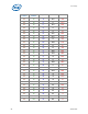
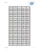
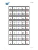
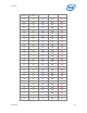
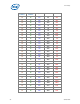
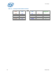
Table 16 - 1 kohm Measurements
Resistor Ball
Resistor Ball
AM5 AH9
AM7 AH9
AJ1 AJ2
AD2 AF2
AG2 AG3
AJ3 AK3
AD1 AC1
AF1 AB2
AE1 AG1
R3 Y1
F28 G28
F3 G23
A13 T1
B23 C22
AL1 AK1
G2 R1
H1 AL2
AJ7 AH7
AC2 AE8
N4 P5
AC4 AE4
AH4 AH5
AJ5 AJ6
AB3 AD3
H4 M2
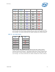
Note: Changes from Test Chip JM8HKZLVA to Test Chip JM8YKZLVA Summary
VSS pads (AL3, U1, G1, E29, A24, AN7) are not used.
Pad (D14) replaces pad (E7) as an Hcontrol signal. E7 is not used.
Pad (E6) replaces pad (F6) as an Hcontrol signal. F6 is not used
Pads (E23, F23) are not used.
VSS pads (AH7, AJ7, AL7, AM7) became signals that are tested resistively.
VCC pad (AL8) has become a signal that is tested resistively.
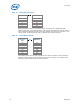
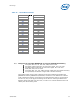
The following table can be used to identify the electrical differences between the
JM8HKZLVA and the JM8YKZLVA (LGA775YP) test devices. The differences could be
used to determine that the correct device and manufacturing test are synchronized
and not rely only on the physical markings of the devices. Testing the differences
between which land pads have zero ohm, 1 kohm or no resistors between them can
identify the devices being used.