
Guide

Intel Celeron M Processor Front Side Bus Design Guidelines
R
64 Intel
®
852GM Chipset Platform Design Guide
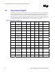
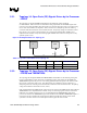
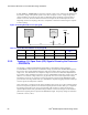
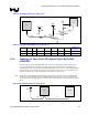
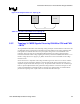
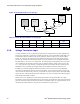
5.5. Asynchronous Signals
The following sections describe the topologies and layout recommendations for the Asynchronous Open
Drain and CMOS signals found on the platform. All Open Drain signals listed in the following sections
must be pulled-up to VCCP (1.05 V). If any of these Open Drain signals are pulled-up to a voltage
higher than VCCP, the reliability and power consumption of the processor may be affected. Therefore, it
is very important to follow the recommended pull-up voltage for these signals. All signals must meet the
AC and DC specifications as documented in the Intel
®
Celeron
®
M Processor Datasheet.
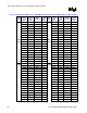
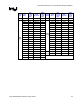
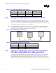
Table 20. Asynchronous AGTL+ Nets
Signal
Names
Description Topology
#
CPU IO
Type
Output Output
Buffer
Type
Input Input Power
Well
A20M# Address 20
mask
2C I ICH4-M CMOS CPU N/A
DPSLP# Deep sleep 2B I ICH4-M CMOS CPU N/A
FERR# Floating point
error
1B O CPU AGTL+ ICH4-M Main I/O (3.3
V)
IERR# Internal error 1A O CPU AGTL+ System
Receiver
Vcc_Receiver
IGNNE# Ignore next
numeric error
2C I ICH4-M CMOS CPU N/A
INIT# Processor
initialize
3 I ICH4-M CMOS CPU,
FWH
N/A, 3.3V
LINT0/INTR Local
interrupts
2C I ICH4-M CMOS CPU N/A
LINT1/NMI Local
interrupts
2C I ICH4-M CMOS CPU N/A
PROCHOT# Thermal
sensor
1C O CPU AGTL+ System
Receiver
Vcc_Receiver
PWRGOOD System power
good
2A I ICH4-M OD
CMOS
CPU N/A
SLP# Sleep 2C I ICH4-M CMOS CPU N/A
SMI# System
management
interrupt
2C I ICH4-M CMOS CPU N/A
STPCLK# Processor stop
clock
2C I ICH4-M CMOS CPU N/A
THRMTRIP# Thermal
sensor
1B O CPU AGTL+ System
Receiver
Vcc_Receiver