
Guide

Platform Design Checklist
R
Intel
®
852GM Chipset Platform Design Guide 265
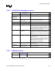
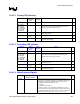
14.8.12. Primary IDE Interface
Pin Name System
Pull-up/Pull-
down
Series
Damping
Notes
9
IDE_PDD[15:0]
These signals have integrated series resistors.
IDE_PDA[2:0],
IDE_PDCS1#,
IDE_PDCS3#,
IDE_PDDACK#,
IDE_PDIOW#,
IDE_PDIOR#
These signals have integrated series resistors. Pads for
series resistors can be implemented should the system
designer have signal integrity concerns.
IDE_PDDREQ
These signals have integrated series resistors and pull-down
resistors in ICH4-M.
IDE_PIORDY
4.7 k
Ω pull-up
to Vcc3_3
This signal has integrated series resistor in ICH4-M.
IDE_PRST#
22-47
Ω
The signal must be buffered to provide IDE_RST# for
improved signal integrity.
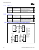
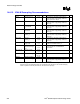
14.8.13. Secondary IDE Interface
Pin Name System
Pull-up/Pull-
down
Series
Damping
Notes
9
IDE_SDD[15:0] These signals have integrated series resistors.
IDE_SDA[2:0],
IDE_SDCS1#,
IDE_SDCS3#,
IDE_SDDACK#,
IDE_SDIOW#,
IDE_SDIOR#
These signals have integrated series resistors. Pads for
series resistors can be implemented should the system
designer have signal integrity concerns.
IDE_SDDREQ
These signals have integrated series resistors and pull-down
resistors in ICH4-M.
IDE_SIORDY
4.7 k
Ω pull-up
to Vcc3_3
This signal has integrated series resistor in ICH4-M.
IDE_SRST#
22-47
Ω
The signal must be buffered to provide IDE_RST# for
improved signal integrity..
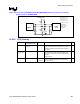
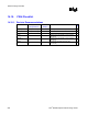
14.8.14. Miscellaneous Signals
Pin Name System
Pull-up/Pull-down
Notes
9
SPKR SPKR is a strapping option for the TCO Timer Reboot function and is
sampled on the rising edge of PWROK. An integrated weak pull-down
is enabled only at boot/reset. Status of strap is readable via the
NO_REBOOT bit (D31:F0, Offset D4h, bit 1).
1 = disabled
0 = enabled (normal operation)
To disable, a jumper can be populated to pull SPKR high. Value of
pull-up must be such that the voltage divider output caused by the pull-
up, effective impedance of speaker and codec circuit, and internal pull-
down will be read as logic high (0.5 * Vcc3_3 to Vcc3_3 + 0.5).