
Guide


Intel 852GM Platform Power Delivery Guidelines
R
Intel
®
852GM Chipset Platform Design Guide 231
12.5.5. ICH4-M Decoupling / Power Delivery Guidelines
12.5.5.1. ICH4-M Decoupling
The ICH4-M is capable of generating large current swings when switching between logic high and logic
low. This condition could cause the component voltage rails to drop below specified limits. To avoid
this type of situation, ensure that the appropriate amount of decoupling capacitance is added in parallel
to the voltage input pins. Intel recommends that the developer use the amount of high frequency
decoupling capacitors specified in table below to ensure that component maintains stable supply
voltages. Low frequency decoupling is dependent on layout and system power supply design.
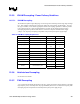
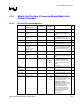
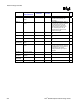
Table 95. ICH4-M Decoupling Requirements
Pin Name Configuration F Qty
VCC3_3 Connect to Vcc3_3S 0.1 µF 6
VCCSUS3_3 Connect to Vcc3_3A 0.1 µF 2
VCCLAN3_3 Connect to Vcc3_3 0.1 µF 2
V_CPU_IO Connect to Vccp IMVP-IV / III 1 µF
1 µF
1
1
VCC1_5 Connect to Vcc1_5S 0.1 µF 2
VCCSUS1_5 Connect to Vcc1_5A 0.1 µF 2
VCCLAN1_5 Connect to Vcc1_5 0.1 µF 2
V5REF Connect to Vcc5_Ref 0.1 µF 1
V5REF_SUS Connect to Vcc5A 0.1 µF 1
VCCRTC Connect to Vcc_RTC 0.1 µF 1
VCCHI Connect to Vcc1_5S 0.1 µF 2
0.1 µF 1
VCCPLL Connect to Vcc1_5S
0.01 µF 1
NOTE: Capacitors should be placed less than 100 mils from the package.
12.5.6. Hub Interface Decoupling
See Section 9.4 for details.
12.5.7. FWH Decoupling
A 0.1-µF capacitor should be placed between the VCC supply pins and the VSS ground pins to decouple
high frequency noise, which may affect the programmability of the device. Value of low frequency bulk
decoupling capacitor is dependent on board layout and system power supply design.