
2 Note

Using Voltage Identifier (VID) Signals
307507-002 15
damage, drive only one control signal high at any time during the test while all others
are low.
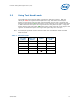
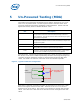
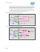
The High Side switch of each switch pair is used to test a VCCP solder ball and contact
along with the shared signal solder ball and contact of the High and Low Side switch
pair. The control line for the High Side switch is driven to a logic high, thus turning
the switch ON and enabling an electrical connection between VCCP and the shared
signal. When this happens, a logic high should be received on the shared signal. At
the same time, the Low Side switch control signal will be at a logic low.
The Low Side switch of each switch pair is used to test a GND solder ball and contact
along with the shared signal solder ball and contact of the High and Low Side switch
pair. The control line for the Low Side switch is driven to a logic high, thus turning the
switch ON and enabling an electrical connection between GND and the shared signal.
A logic low should be received on the shared signal. At the same time, the High Side
switch control signal will be at a logic low.
One shared signal is used to test one VCCP and one GND connection. The lack of the
high/low signal transition would indicate an open on either the shared signal or the
power/ground connection used by that switch pair.
Figure 2 shows that Signal1, Vccp1, and Gnd1 as well as Signal2, Vccp2, and
Gnd2 can be verified through Hcontrol_0 and Lcontrol_0.
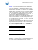
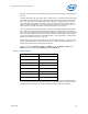
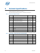
Table 5 - Control Signals
As with all powered digital
in-circuit testing, all other active components on the board that are connected to the
socket should be placed in a tri-state mode before testing with this technique.
Signal Name Signal Ball
Hcontrol_0
U2
Lcontrol_0
J16
Hcontrol_1
U3
Lcontrol_1
H15
Hcontrol_2
D14
Lcontrol_2
H16
Hcontrol_3
E6
Lcontrol_3
J17