
Guide

Integrated Graphics Display Port
R
130 Intel
®
852GM Chipset Platform Design Guide
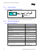
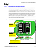
8.1.3. RAMDAC Board Design Guidelines
In order for the RAMDAC to successfully run at speeds up to 350 MHz, care should be taken when
routing the analog RAMDAC signals. Intel recommends that each analog R, G, B signal be routed
single-endedly. The analog RGB signals should be routed with an impedance of 37.5 Ω. Intel
recommends that these routes be routed on an inner routing layer and that it be shielded with VSS
planes, if possible. Spacing between R, G, and B channels and to other signals should be maximized;
20-mil spacing is recommended. The RGB signals require pi filters that should be placed near the VGA
connector. It consists of two 3.3-pF caps with a 75 Ω at 100-MHz FB between them. The RGB signals
should have a 75-Ω, 1% terminating pull-down resistor. The complement signals (R#, G#, and B#)
should be grounded to the ground plane.
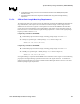
Intel recommends that the pi filter and terminating resistors be placed as close as possible to the VGA
connector. After the 75-Ohm termination resistor, the RGB signals should continue on to their pi filters
and the VGA connector, but should now ideally be routed with a 75-Ohm impedance (~ 5 mil traces).
The RGB signals also require protection diodes between 1.5 V and ground. These diodes should have
low C ratings (~5 pF max) and small leakage current (~ 10 µA at 120˚C) and should be properly
decoupled with a 0.1-µF cap. These diodes and decoupling should be placed to minimize power rail
inductance. The choice between diodes (or diode packs) should comprehend the recommended electrical
characteristics in addition to cost.
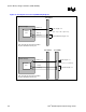
The RGB signals should be length matched as closely as possible (from the Intel 852GM GMCH to
VGA connector) and should not exceed 200 mils of mismatch.