
Intel Celeron Processor in the 478-Pin Package at 1.80 GHz Datasheet


76 Datasheet
Intel
®
Celeron
®
Processor in the 478-Pin Package
LINT[1:0] Input
LINT[1:0] (Local APIC Interrupt) must connect the appropriate pins of all APIC
Bus agents. When the APIC is disabled, the LINT0 signal becomes INTR, a
maskable interrupt request signal, and LINT1 becomes NMI, a nonmaskable
interrupt. INTR and NMI are backward compatible with the signals of those
names on the Pentium processor. Both signals are asynchronous.
Both of these signals must be software configured via BIOS programming of the
APIC register space to be used either as NMI/INTR or LINT[1:0]. Because the
APIC is enabled by default after Reset, operation of these pins as LINT[1:0] is the
default configuration.
LOCK#
Input/
Output
LOCK# indicates to the system that a transaction must occur atomically. This
signal must connect the appropriate pins of all processor system bus agents. For
a locked sequence of transactions, LOCK# is asserted from the beginning of the
first transaction to the end of the last transaction.
When the priority agent asserts BPRI# to arbitrate for ownership of the processor
system bus, it will wait until it observes LOCK# deasserted. This enables
symmetric agents to retain ownership of the processor system bus throughout the
bus locked operation and ensure the atomicity of lock.
MCERR#
Input/
Output
MCERR# (Machine Check Error) is asserted to indicate an unrecoverable error
without a bus protocol violation. It may be driven by all processor system bus
agents.
MCERR# assertion conditions are configurable at a system level. Assertion
options are defined by the following options:
• Enabled or disabled.
• Asserted, if configured, for internal errors along with IERR#.
• Asserted, if configured, by the request initiator of a bus transaction after it
observes an error.
• Asserted by any bus agent when it observes an error in a bus transaction.
For more details regarding machine check architecture, refer to the IA-32
Software Developer’s Manual, Volume 3: System Programming Guide.
PROCHOT# Output
PROCHOT# will go active when the processor temperature monitoring sensor
detects that the processor has reached its maximum safe operating temperature.
This indicates that the processor Thermal Control Circuit has been activated, if
enabled. See Section 7.3 for more details.
PWRGOOD Input
PWRGOOD (Power Good) is a processor input. The processor requires this
signal to be a clean indication that the clocks and power supplies are stable and
within their specifications. ‘Clean’ implies that the signal will remain low (capable
of sinking leakage current), without glitches, from the time that the power supplies
are turned on until they come within specification. The signal must then transition
monotonically to a high state. Figure 12 illustrates the relationship of PWRGOOD
to the RESET# signal. PWRGOOD can be driven inactive at any time, but clocks
and power must again be stable before a subsequent rising edge of PWRGOOD.
It must also meet the minimum pulse width specification in Table 16, and be
followed by a 1 to 10 ms RESET# pulse.
The PWRGOOD signal must be supplied to the processor; it is used to protect
internal circuits against voltage sequencing issues. It should be driven high
throughout boundary scan operation.
REQ[4:0]#
Input/
Output
REQ[4:0]# (Request Command) must connect the appropriate pins of all
processor system bus agents. They are asserted by the current bus owner to
define the currently active transaction type. These signals are source
synchronous to ADSTB0#. Refer to the AP[1:0]# signal description for a details
on parity checking of these signals.
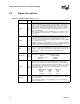
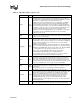
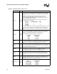
Table 32. Signal Description (Sheet 5 of 7)
Name Type Description