
Guide
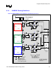

Integrated Graphics Display Port
R
136 Intel
®
852GM Chipset Platform Design Guide
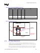
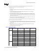
8.2.1.1. Package Length Compensation
As mentioned in Section 8.2.1, all length matching is done from GMCH die-pad to LVDS connector
pin. The reason for this is to compensate for the package length variation across each signal group in
order to minimize timing variance. The GMCH does not equalize package lengths internally as some
previous GMCH components have, and therefore, the GMCH requires a length matching process. See
Table 52 for the Intel 852GM LVDS package lengths information.
Package length compensation should not be confused with length matching as discussed in the previous
section. Length matching refers to constraints on the minimum and maximum length bounds of a signal
group based on clock length, whereas package length compensation refers to the process of adjusting
out package length variance across a signal group. There is of course some overlap in that both affect
the target length of an individual signal. Intel recommends that the initial route be completed based on
the length matching formulas in conjunction with nominal package lengths and that package length
compensation is performed as a secondary operation.
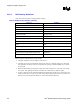
8.2.2. LVDS Routing Guidelines
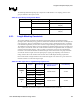
Table 51. LVDS Signal Group Routing Guidelines
Parameter Definition
Signal Group LVDS
Topology Differential Pair Point to Point
Reference Plane Ground Referenced
Differential Mode Impedance (Zdiff) 100 ohms ± 15%
Nominal Trace Width 4 mils
Nominal Pair Spacing (edge to edge) 7 mils
Minimum Pair to Pair Spacing
(see exceptions for breakout region below)
20 mils
Minimum Serpentine Spacing 20 mils
Minimum Spacing to Other LVDS Signals
(see exceptions for breakout region below)
20 mils
Minimum Isolation Spacing to non-LVDS Signals 20 mils
Maximum Via Count 2 (per line)
Package Length Range – P1
550 mils ± 150mils
(see LVDS package length Table 52 for exact lengths)
Total Length – Max 10”
Clock Length Matching Match all segments to ± 20 mils (see Section 8.2.1)
Clock to Clock Length Matching (Total Length) Match clocks to X0 ± 20 mils
Breakout Exceptions
(Reduced geometries for GMCH breakout region)
Breakout section should be as shorter as possible. Try to
maintain trace width as 4 mils, spacing 7 mils, while the spacing
between pairs can be 10-20 mils.