
Intel Celeron Processor in the 478-Pin Package at 1.80 GHz Datasheet

Datasheet 43
Intel
®
Celeron
®
Processor in the 478-Pin Package
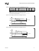
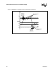
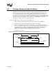
3.2.1 Overshoot/Undershoot Guidelines
Overshoot (or undershoot) is the absolute value of the maximum voltage above the nominal high
voltage (or below V
SS) as shown in Figure 21. The overshoot/undershoot guidelines limit
transitions beyond V
CC or VSS due to the fast signal edge rates. The processor can be damaged by
repeated overshoot or undershoot events on any input, output, or I/O buffer if the charge is large
enough (i.e., if the over/undershoot is great enough). Determining the impact of an overshoot/
undershoot condition requires knowledge of the magnitude, the pulse direction, and the activity
factor (AF) of the incident waveform. Permanent damage to the processor is the likely result of
excessive overshoot/undershoot.
When performing simulations to determine impact of overshoot and undershoot, ESD diodes must
be properly characterized. ESD protection diodes do not act as voltage clamps and will not provide
overshoot or undershoot protection. ESD diodes modelled within Intel I/O buffer models do not
clamp undershoot or overshoot and will yield correct simulation results. If other I/O buffer models
are being used to characterize the Celeron
processor in the 478-pin package system bus, care must
be taken to ensure that ESD models do not clamp extreme voltage levels. Intel I/O buffer models
also contain I/O capacitance characterization. Therefore, removing the ESD diodes from an I/O
buffer model will impact results and may yield excessive overshoot/undershoot.
3.2.1.1 Overshoot/Undershoot Magnitude
Magnitude describes the maximum potential difference between a signal and its voltage reference
level. For the Celeron
processor in the 478-pin package both are referenced to VSS. It is important
to note that overshoot and undershoot conditions are separate and their impact must be determined
independently.
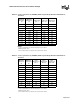
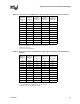
Overshoot/undershoot magnitude levels must observe the absolute maximum specifications listed
in Table 22 through Table 25. These specifications must not be violated at any time regardless of
bus activity or system state. Within these specifications are threshold levels that define different
allowed pulse durations. Provided that the magnitude of the overshoot/undershoot is within the
absolute maximum specifications (2.3 V for overshoot and -0.65 V for undershoot), the pulse
magnitude, duration and activity factor must all be used to determine if the overshoot/undershoot
pulse is within specifications.
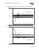
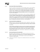
3.2.1.2 Overshoot/Undershoot Pulse Duration
Pulse duration describes the total time an overshoot/undershoot event exceeds the overshoot/
undershoot reference voltage (maximum overshoot = 2.3 V, maximum undershoot = -0.65 V). The
total time could encompass several oscillations above the reference voltage. Multiple overshoot/
undershoot pulses within a single overshoot/undershoot event may need to be measured to
determine the total pulse duration.
Note: Oscillations below the reference voltage can not be subtracted from the total overshoot/undershoot
pulse duration.