
Datasheet


Mobile Intel
®
Pentium
®
III Processor in BGA2 and Micro-PGA2 Packages at 1 GHz,
900 MHz, 850 MHz, 800 MHz, 750 MHz, 700 MHz, Low-voltage 750 MHz, Low-voltage 700 MHz,
Low-voltage 600 MHz, Ultra Low-voltage 600 MHz and Ultra Low-voltage 500 MHz
30 Datasheet 283653-002
8. Icc
DSLP
is Deep Sleep Leakage current.
9. Format: (Maximum Performance Mode Parameter) / (Battery Optimized Mode Parameter).
The signals on the mobile Pentium III processor system bus are included in the GTL+ signal
group. These signals are specified to be terminated to V
CC
. The DC specifications for these signals
are listed in
Table 10 and the termination and reference voltage specifications for these signals are listed in
Table 11.
The mobile Pentium III processor requires external termination and a V
REF
. Refer to the Mobile
Pentium III Processor GTL+ System Bus Layout Guideline for full details of system V
CCT
and
V
REF
requirements. The CMOS, Open-drain, and TAP signals are designed to interface at 1.5V
levels to allow connection to other devices. BCLK and PICCLK are designed to receive a 2.5-V
clock signal. The DC specifications for these signals are listed Table 12.
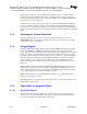
Table 10. GTL+ Signal Group DC Specifications
T
J
= 0°C to 100°C; T
J
= 5°C to 100°C for Vcc = 1.15V; V
CC
= 0.975V ±25 mV or 1.10V ±80 mV or 1.15V
±80 mV or 1.35V ±100 mV or 1.60V ±115 mV or 1.70V -80/+125 mV ; V
CCT
= 1.50V ±115 mV
Symbol Parameter Min Max Unit Notes
V
OH
Output High Voltage — — V See V
CCT,max
in
Table 11
R
ON
Output Low Drive Strength 16.67
Ω
I
L
Leakage Current for Inputs, Outputs and I/Os ±100
µA
Note 1
NOTE: (0 ≤ V
IN/OUT
≤ V
CCT
).
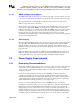
Table 11. GTL+ Bus DC Specifications
T
J
= 0°C to 100°C; T
J
= 5°C to 100°C for Vcc = 1.15V; V
CC
= 0.975V ±25 mV or 1.10V ±80 mV or 1.15V
±80 mV or 1.35V ±100 mV or 1.60V ±115 mV or 1.70V -80/+125 mV ; V
CCT
= 1.50V ±115 mV
Symbol Parameter Min Typ Max Unit Notes
V
CCT
Bus Termination Voltage 1.385 1.5 1.615 V Note 1
V
REF
Input Reference Voltage
2
/
3
V
CCT
– 2%
2
/
3
V
CCT
2
/
3
V
CCT
+ 2% V ±2%, Note 2
R
TT
Bus Termination Strength 50 56 65
Ω
On-die R
TT
,
Note 3
NOTES:
1. For simulation use 1.50V ±10%. For typical simulation conditions use V
CCTmin
(1.5V –10%).
2. V
REF
should be created from V
CCT
by a voltage divider.
3. The RESET# signal does not have an on-die R
TT
. It requires an off-die 56.2Ω ±1% terminating resistor
connected to V
CCT
.