
Specification Sheet


Thermal Management
108 Datasheet, Volume 1 of 2
The Ψ
CA
point at DTS = -1 defines the minimum Ψ
CA
required at TDP considering the
worst case system design T
AMBIENT
design point:
Ψ
CA
= (T
CASE-MAX
– T
AMBIENT-TARGET
) / TDP
For example, for a 91 W TDP part, the T
CASE
maximum is 63.7 °C and at a worst case
design point of 40 °C local ambient this will result in:
Ψ
CA
= (63.7 – 40) / 91 = 0.26 °C/W
Similarly for a system with a design target of 45 °C ambient, the Ψ
CA
at DTS = -1
needed will be 0.21 °C/W.
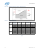
The second point defines the thermal solution performance (Ψ
CA
) at T
CONTROL
. The
following table lists the required Ψ
CA
for the various TDP processors.
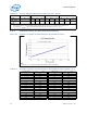
These two points define the operational limits for the processor for DTS 1.1
implementation. At T
CONTROL
the fan speed must be programmed such that the
resulting Ψ
CA
is better than or equivalent to the required Ψ
CA
listed in the following
table. Similarly, the fan speed should be set at DTS = -1 such that the thermal solution
performance is better than or equivalent to the ΨCA requirements at T
AMBIENT-MAX
.
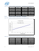
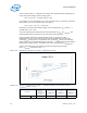
The fan speed controller must linearly ramp the fan speed from processor
DTS = T
CONTROL
to processor DTS = -1.
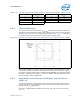
Figure 5-6. Digital Thermal Sensor (DTS) 1.1 Definition Points
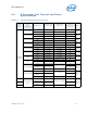
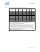
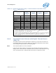
Table 5-12. Digital Thermal Sensor (DTS) 1.1 Thermal Solution Performance Above
T
CONTROL
(Sheet 1 of 2)
Processor
Ψ
CA
at DTS =
T
CONTROL
1, 2
At System
T
AMBIENT_MAX
= 30 °C
Ψ
CA
at DTS = -1
At System
T
AMBIENT_MAX
= 40 °C
Ψ
CA
at DTS = -1
At System
T
AMBIENT_MAX
= 45 °C
Ψ
CA
at DTS = -1
At System
T
AMBIENT_MAX
= 50 °C
8-Core GT2 95W 0.44 0.263 0.211 0.158