
Specification Sheet


Thermal Management
102 Datasheet, Volume 1 of 2
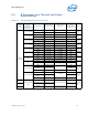
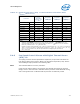
Table 5-6. Low Power and TTV Specifications (S-Processor Line)
Processor IA Cores,
Graphics
Configuration and
TDP
PCG
7
Max Power
Package C7
(W)
1,4,5
Max Power
Package C8
(W)
1,4,5
TTV TDP
(W)
6,7
Min
T
CASE
(°C)
Max TTV
T
CASE
(°C)
8-Core GT2 95W 2015D N/A N/A 95 0 65
6-Core GT2 95W 2015D N/A N/A 95 0 65
4-Core GT2 91W 2015D N/A N/A 91 0 65
6-Core GT2 65W 2015C N/A N/A 65 0 71
4-Core GT2 65W 2015C N/A N/A 65 0 71
4-Core GT2 62W 2015C N/A N/A 62 0 70
6-Core GT2 35W 2015B N/A N/A 35 0 66
4-Core GT2 35W 2015B N/A N/A 35 0 66
2-Core GT2/GT1 54W 2015C N/A N/A 54 0 66
2-Core GT2/GT1 58W 2015C N/A N/A 58 0 68
2-Core GT2/GT1 35W 2015B N/A N/A 35 0 66
Notes:
1. The package C-state power is the worst case power in the system configured as follows:
a. Memory configured for DDR4 2400 and populated with two DIMMs per channel.
b. DMI and PCIe links are at L1
2. Specification at DTS = 50 °C and minimum voltage loadline.
3. Specification at DTS = 35 °C and minimum voltage loadline.
4. These DTS values in Notes 2 - 3 are based on the TCC Activation MSR having a value of 100, Refer
Chapter 5, “Thermal Management Features”.
5. These values are specified at V
CC_MAX and VNOM for all other voltage rails for all processor frequencies.
Systems should be designed to ensure the processor is not to be subjected to any static V
CC and ICC
combination wherein VCCP exceeds VCCP_MAX at specified ICCP. Refer the loadline specifications.
6. Thermal Design Power (TDP) should be used for processor thermal solution design targets. TDP is not the
maximum power that the processor can dissipate. TDP is measured at DTS = -1.TDP is achieved with the
Memory configured for DDR4 2400/2666 2 DIMMs per channel.
7. Platform Compatibility Guide (PCG) (previously known as FMB) provides a design target for meeting all
planned processor frequency requirements.
8. Not 100% tested. Specified by design characterization.