
User Manual


Datasheet 5
Figures
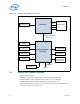
1-1 Platform Block Diagram Example ......................................................................... 10
1-2 PCI Express* Lane Partitioning and Direct Media Interface Gen 2 (DMI2) .................. 13
2-1 PCI Express* Layering Diagram........................................................................... 21
2-2 Packet Flow through the Layers........................................................................... 21
5-1 Input Device Hysteresis ..................................................................................... 40
5-2 Voltage Regulator (VR) Power State Transitions..................................................... 44
5-3 Serial VID Interface (SVID) Signals Clock Timings ................................................. 53
5-4 V
CCIN
Static and Transient Tolerance Loadlines...................................................... 55
5-5 V
CCIN
Overshoot Example Waveform.................................................................... 56
5-6 BCLK{0/1} Differential Clock Measurement Point for Ringback ................................ 59
5-7 BCLK{0/1} Differential Clock Cross Point Specification ........................................... 59
5-8 BCLK{0/1} Single-Ended Clock Measurement Points for Absolute Cross Point and
Swing60
5-9 BCLK{0/1} Single-Ended Clock Measure Points for Delta Cross Point ........................ 60
Tables
1-1 Terminology ..................................................................................................... 15
1-2 Related Publications........................................................................................... 18
1-3 Public Publications ............................................................................................. 18
4-1 Memory Channel DDR0, DDR1, DDR2, DDR3......................................................... 31
4-2 Memory Channel Miscellaneous ........................................................................... 32
4-3 PCI Express Port 1 Signals.................................................................................. 32
4-4 PCI Express* Port 2 Signals ................................................................................ 32
4-5 PCI Express* Port 3 Signals ................................................................................ 33
4-6 PCI Express* Miscellaneous Signals ..................................................................... 33
4-7 Direct Media Interface 2 (DMI2) Signals ............................................................... 33
4-8 Intel QPI Port 0 and 1 Signals ............................................................................. 34
4-9 Platform Environment Control Interface (PECI) Signal ............................................ 34
4-10 System Reference Clock (BCLK{0/1}) Signals ....................................................... 34
4-11 JTAG and TAP Signals ........................................................................................ 34
4-12 SVID Signals .................................................................................................... 35
4-13 Processor Asynchronous Sideband Signals ............................................................ 35
4-14 Miscellaneous Signals ........................................................................................ 37
4-15 Power and Ground Signals.................................................................................. 38
5-1 Power and Ground Lands.................................................................................... 41
5-2 SVID Address Usage .......................................................................................... 44
5-3 VR12.5 Reference Code Voltage Identification (VID) Table ...................................... 45
5-4 Signal Description Buffer Types ........................................................................... 47
5-5 Signal Groups ................................................................................................... 47
5-6 Signals with On-Die Weak Pull-Up/Pull-Down Resistors........................................... 50
5-7 Power-On Configuration Option Lands .................................................................. 50
5-8 Processor Absolute Minimum and Maximum Ratings............................................... 51
5-9 Storage Condition Ratings .................................................................................. 52
5-10 Voltage Specification.......................................................................................... 53
5-11 Current (I
CCIN_MAX
and I
CCIN_TDC
) Specification ..................................................... 54
5-12 V
CCIN
Static and Transient Tolerance Processor...................................................... 54
5-13 V
CCIN
Overshoot Specifications............................................................................ 56
5-14 DDR4 Signal DC Specifications ............................................................................ 56