
User Manual

Datasheet 39
Electrical Specifications
5 Electrical Specifications
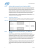
5.1 Integrated Voltage Regulation
A new feature to the processor is the integration of platform voltage regulators into the
processor. Due to this integration, the processor has one main voltage rail (V
CCIN
) and
a voltage rail for the memory interface (V
CCD01,
V
CCD23
– one for each memory channel
pair), compared to five voltage rails (V
CC
, V
TTA
, V
TTD
, V
SA
, and V
CCPLL
) on previous
processors. The V
CCIN
voltage rail will supply the integrated voltage regulators, which
in turn will regulate to the appropriate voltages for the cores, cache, and system
agents. This integration allows the processor to better control on-die voltages to
optimize for both performance and power savings. The processor V
CCIN
rail will remain
a VID-based voltage with a loadline similar to the core voltage rail (called V
CC
) in
previous processors.
5.2 Processor Signaling
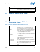
The processor includes 2011 lands that use various signaling technologies. Signals are
grouped by electrical characteristics and buffer type into various signal groups. These
include DDR4 (Reference Clock, Command, Control, and Data), PCI Express*, DMI2,
Intel
®
QuickPath Interconnect, Platform Environmental Control Interface (PECI),
System Reference Clock, SMBus, JTAG and Test Access Port (TAP), SVID Interface,
Processor Asynchronous Sideband, Miscellaneous, and Power/Other signals. Refer to
Table 5-5, “Signal Groups” on page 47 for details.
Intel strongly recommends performing analog simulations of all interfaces.
5.2.1 System Memory Interface Signal Groups
The system memory interface uses DDR4 technology that consists of numerous signal
groups. These include: Reference Clocks, Command Signals, Control Signals, and Data
Signals. Each group consists of numerous signals that may use various signaling
technologies. Refer to Table 5-5, “Signal Groups” on page 47 for further details.
Throughout this chapter, the system memory interface may be referred to as DDR4.
5.2.2 PCI Express* Signals
The PCI Express Signal Group consists of PCI Express* ports 1, 2, and 3, and PCI
Express miscellaneous signals. Refer to Table 5-5, “Signal Groups” on page 47 for
further details.
5.2.3 Direct Media Interface 2 (DMI2) / PCI Express* Signals
The Direct Media Interface Gen 2 (DMI2) sends and receives packets and/or commands
to the PCH. The DMI2 is an extension of the standard PCI Express Specification. The
DMI2/PCI Express signals consist of DMI2 receive and transmit input/output signals
and a control signal to select DMI2 or PCIe* 2.0 operation for port 0. Refer to
Table 5-5, “Signal Groups” on page 47 for further details.