
User Manual

Datasheet 37
Signal Descriptions
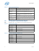
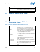
Table 4-14. Miscellaneous Signals (Sheet 1 of 2)
Signal Name Description
BIST_ENABLE
BIST Enable Strap. Input which allows the platform to enable or disable
built-in self test (BIST) on the processor. This signal is pulled up on the die.
Refer to Table 5-6, “Signals with On-Die Weak Pull-Up/Pull-Down Resistors”
on page 50 for details.
BMCINIT
BMC Initialization Strap. Indicates whether Service Processor Boot Mode
should be used. Used in combination with FRMAGENT and SOCKET_ID
inputs.
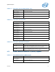
0 = Service Processor Boot Mode Disabled. Example boot modes: Local PCH
(this processor hosts a legacy PCH with firmware behind it), Intel QPI
Link Boot (for processors one hop away from the FW agent), or Intel
QPI Link Init (for processors more than one hop away from the
firmware agent).
1 = Service Processor Boot Mode Enabled. In this mode of operation the
processor performs the absolute minimum internal configuration and
then waits for the Service Processor to complete its initialization. The
socket boots after receiving a "GO" handshake signal using a firmware
scratchpad register.
This signal is pulled down on the die. Refer to Table 5-6, “Signals with On-
Die Weak Pull-Up/Pull-Down Resistors” on page 50 for details.
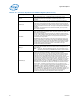
DEBUG_EN_N
This pin is used to force debug to be enabled when the ITP is connected to
the main board. This allows debug to occur beginning from cold boot.
EAR_N
External Alignment of Reset, used to bring the processor up into a
deterministic state. This signal is pulled up on the die. Refer to Table 5-6,
“Signals with On-Die Weak Pull-Up/Pull-Down Resistors” on page 50 for
details.
FIVR_FAULT
Indicates an internal error has occurred with the integrated voltage
regulator. The FIVR_FAULT signal can be sampled any time after 1.5 ms
after the assertion of PWRGOOD. FIVR_FAULT must be qualified by
THERMTRIP_N assertion.
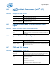
FRMAGENT
Bootable Firmware Agent Strap. This input configuration strap used in
combination with SOCKET_ID to determine whether the socket is a legacy
socket, bootable firmware agent is present, and DMI links are used in PCIe*
mode (instead of DMI2 mode).
The firmware flash ROM is located behind the local PCH attached to the
processor using the DMI2 interface.This signal is pulled down on the die.
Refer to Table 5-6, “Signals with On-Die Weak Pull-Up/Pull-Down Resistors”
on page 50 for details.
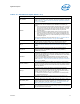
PM_FAST_WAKE_N
Power Management Fast Wake. Enables quick package C3–C6 exits of all
sockets. Asserted if any socket detects a break from package C3–C6 state
requiring all sockets to exit the low-power state to service a snoop, memory
access, or interrupt. Expected to be wired-OR among all processor sockets
within the platform.
PROC_ID
This output can be used by the platform to determine if the installed
processor is an Intel
®
Core™ processor family for the LGA2011-v3 socket
processor or a future processor planned for the platforms. There is no
connection to the processor silicon for this signal. The processor package
grounds or floats the pin to set ‘0’ or ‘1’, respectively.
1 = Intel
®
Core™ processor family for the LGA2011-v3 socket processor
0 = Reserved for future use
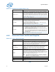
RSVD
RESERVED. All signals that are RSVD must be left unconnected on the
board. Refer to Section 5.2.9, “Reserved or Unused Signals” for details.
SAFE_MODE_BOOT
Safe Mode Boot Strap. SAFE_MODE_BOOT allows the processor to wake up
safely by disabling all clock gating. This allows BIOS to load registers or
patches if required. This signal is sampled after PWRGOOD assertion. The
signal is pulled down on the die. Refer to Table 5-6, “Signals with On-Die
Weak Pull-Up/Pull-Down Resistors” on page 50 for details.
SKTOCC_N
SKTOCC_N (Socket Occupied) is used to indicate that a processor is present.
This is pulled to ground on the processor package. There is no connection to
the processor silicon for this signal.