
Specification Sheet


Intel
®
Xeon
®
Processor E5-1600/E5-2600/E5-4600 v2 Product Families 71
Datasheet Volume One of Two
Interfaces
2.5.2.10.3 WrPCIConfigLocal() Capabilities
On the processor PECI clients, the PECI WrPCIConfigLocal() command provides a
method
for programming certain integrated memory controller and IIO functions as
described in Table 2-15. Refer to the Intel® Xeon® Processor E5 v2 Product Family
Processor Datasheet, Volume Two: Registers for more details on specific register
definitions. It also enables writing to processor REUT (Robust Electrical Unified Test)
registers associated with the Intel® QPI, PCIe* and DDR3 functions.
2.5.3 Client Management
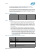
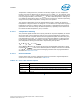
2.5.3.1 Power-up Sequencing
The PECI client will not be available when the PWRGOOD signal is de-asserted. Any
transactions on the bus during this time will be completely ignored, and the host will
read the response from the client as all zeroes. PECI client initialization is completed
approximately 100 µS after the PWRGOOD assertion. This is represented by the start of
the PECI Client “Data Not Ready” (DNR) phase in Figure 2-49. While in this phase, the
PECI client will respond normally to the Ping() and GetDIB() commands and return the
highest processor die temperature of 0x0000 to the GetTemp() command. All other
commands will get a ‘Response Timeout’ completion in the DNR phase as shown in
Table 2-16. All PECI services with the exception of core MSR space accesses become
available ~500 µS after RESET_N de-assertion as shown in Figure 2-49. PECI will be
fully functional with all services including core accesses being available when the core
comes out of reset upon completion of the RESET microcode execution.
In the event of the occurrence of a fatal or catastrophic error, all PECI services with the
exception of core MSR space accesses will be available during the DNR phase to
facilitate debug through configuration space accesses.
CC: 0x91 PECI control hardware, firmware or associated logic error. The processor is unable to process
the request.
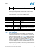
Table 2-14. WrPCIConfigLocal() Response Definition (Sheet 2 of 2)
Response Meaning
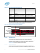
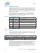
Table 2-15. WrPCIConfigLocal() Memory Controller and IIO Device/Function Support
Bus Device Function Offset Range Description
0000 0-5 0-7 000-FFFh Integrated I/O (IIO) Configuration Registers
0001 15 0 104h-127h Integrated Memory Controller 0 MEM_HOT_N Registers
0001 15 0 180h-1AFh Integrated Memory Controller 0 SMBus Registers
0001 15 1 080h-0CFh Integrated Memory Controller 0 RAS Registers
(Scrub/Spare)
0001 16 0, 1, 4, 5 104h-18Bh
1F4h-1FFh
Integrated Memory Controller 0 Thermal Control Registers
0001 16 2, 3, 6, 7 104h-147h Integrated Memory Controller 0 Error Registers
0001 29 0 104h-127h Integrated Memory Controller 1 MEM_HOT_N Registers
0001 29 0 180h-1AFh Integrated Memory Controller 1 SMBus Registers
0001 29 1 080h-0CFh Integrated Memory Controller 1 RAS Registers
(Scrub/Spare)
0001 30 0, 1, 4, 5 104h-18Bh
1F4h-1FFh
Integrated Memory Controller 1 Thermal Control Registers
0001 30 2, 3, 6, 7 104h-147h Integrated Memory Controller 1 Error Registers