
Specification Sheet


Intel
®
Xeon
®
Processor E5-1600/E5-2600/E5-4600 v2 Product Families 219
Datasheet Volume One of Two
Package Mechanical Specifications
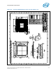
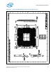
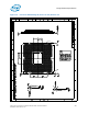
9.3 Processor Component Keep-Out Zones
The processor may contain components on the substrate that define component
keep-out zone requirements. A thermal and mechanical solution design must not
intrude into the required keep-out zones. Do not contact the Test Pad Area with
conductive material. Decoupling capacitors are typically mounted to either the topside
or land-side of the package substrate. See Figure 9-3 through Figure 9-4 for keep-out
zones. The location and quantity of package capacitors may change due to
manufacturing efficiencies but will remain within the component keep-in.
9.4 Package Loading Specifications
Ta b l e 9 - 2 provides load specifications for the processor package. These maximum
limits should not be exceeded during heatsink assembly, shipping conditions, or
standard use condition. Exceeding these limits during test may result in component
failure. The processor substrate should not be used as a mechanical reference or load-
bearing surface for thermal solutions.
.
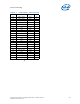
Notes:
1. These specifications apply to uniform compressive loading in a direction normal to the processor IHS.
2. This is the maximum static force that can be applied by the heatsink and Independent Loading Mechanism
(ILM).
3. These specifications are based on limited testing for design characterization. Loading limits are for the
package constrained by the limits of the processor socket.
4. Dynamic loading is defined as an 11 ms duration average load superimposed on the static load
requirement.
5. See Intel® Xeon® Processor E5-1600/2600/4600 v1 and v2 Product Families Thermal / Mechanical Design
Guide for minimum socket load to engage processor within socket.
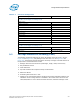
9.5 Package Handling Guidelines
Ta b l e 9 - 3 includes a list of guidelines on package handling in terms of recommended
maximum loading on the processor IHS relative to a fixed substrate. These package
handling loads may be experienced during heatsink removal.
9.6 Package Insertion Specifications
The processor can be inserted into and removed from an LGA2011-0 socket 15 times.
The socket should meet the LGA2011-0 requirements detailed in the
Intel® Xeon®
Processor E5-1600/2600/4600 v1 and v2 Product Families Thermal / Mechanical Design
Guide
.
Table 9-2. Processor Loading Specifications
Parameter Maximum Notes
Static Compressive Load 890 N [200 lbf] 1, 2, 3, 5
Dynamic Load 540 N [121 lbf] 1, 3, 4, 5
Table 9-3. Package Handling Guidelines
Parameter Maximum Recommended Notes
Shear 80 lbs (36.287 kg)
Tensile 35 lbs (15.875 kg)
Torque 35 in.lbs (15.875 kg-cm)