
Specification Sheet


Electrical Specifications
132 Intel
®
Xeon
®
Processor E5-1600/E5-2600/E5-4600 v2 Product Families
Datasheet Volume One of Two
7.1.5 Platform Environmental Control Interface (PECI)
PECI is an Intel proprietary interface that provides a communication channel between
Intel processors and chipset components to external system management logic and
thermal monitoring devices. The processor contains a Digital Thermal Sensor (DTS)
that reports a relative die temperature as an offset from Thermal Control Circuit (TCC)
activation temperature. Temperature sensors located throughout the die are
implemented as analog-to-digital converters calibrated at the factory. PECI provides an
interface for external devices to read processor temperature, perform processor
manageability functions, and manage processor interface tuning and diagnostics.
The PECI interface operates at a nominal voltage set by V
TTD
. The set of DC electrical
specifications shown in Table 7-16 is used with devices normally operating from a V
TTD
interface supply.
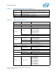
7.1.5.1 Input Device Hysteresis
The PECI client and host input buffers must use a Schmitt-triggered input design for
improved noise immunity. Please refer to Figure 7-1 and Tabl e 7 -1 6.
7.1.6 System Reference Clocks (BCLK{0/1}_DP,
BCLK{0/1}_DN)
The processor core, processor uncore, Intel® QuickPath Interconnect link, PCI
Express* and DDR3 memory interface frequencies) are generated from BCLK{0/1}_DP
and BCLK{0/1}_DN signals. There is no direct link between core frequency and Intel
QuickPath Interconnect link frequency (e.g., no core frequency to Intel QuickPath
Interconnect multiplier). The processor maximum core frequency, Intel QuickPath
Interconnect link frequency and DDR memory frequency are set during manufacturing.
It is possible to override the processor core frequency setting using software.
This permits operation at lower core frequencies than the factory set maximum
core frequency.
The processor core frequency is configured during reset by using values stored within
the device during manufacturing. The stored value sets the lowest core multiplier at
which the particular processor can operate. If higher speeds are desired, the ratio can
be configured via the IA32_PERF_CTL MSR (MSR 199h); Bits [15:0].
Figure 7-1. Input Device Hysteresis
Minimum V
P
Maximum V
P
Minimum V
N
Maximum V
N
PECI High Range
PECI Low Range
Valid Input
Signal Range
Mi ni mum
Hysteresis
V
TTD
PECI Ground