
Specification Sheet


Thermal Management Specifications
112 Intel
®
Xeon
®
Processor E5-1600/E5-2600/E5-4600 v2 Product Families
Datasheet Volume One of Two
5.1.4.2 Embedded Digital Thermal Sensor (DTS) thermal profiles
The thermal solution is expected to be developed in accordance with the Tcase thermal
profile. Operational compliance monitoring of thermal specifications and fan speed
modulation may be done via the DTS based thermal profile.
Each DTS thermal profile is unique to each TDP and core count combination. These
T
DTS
profiles are fully defined by the simple linear equation:
T
DTS
= PSI
PA
* P + T
LA
Where:
PSI
PA
is the Processor-to-Ambient thermal resistance of the processor thermal solution.
T
LA
is the Local Ambient temperature for the Nominal thermal profile.
T
LA-ST
designates the Local Ambient temperature for Short-Term operation.
P is the processor power dissipation.
Tab l e 5 - 4 provides the
PSI
PA
and T
LA
parameters that define T
DTS
thermal profile for
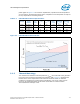
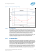
each TDP/Core count combination. Figure 5-4 illustrates the general form of the
resulting linear graph resulting from
T
DTS
= PSI
PA
* P + T
LA
.
The slope of a DTS profile assumes full fan speed which is not required over much of
the power range. Tcontrol is the temperature above which fans must be at maximum
speed to meet the thermal profile requirements. Tcontrol is different for each SKU and
may be slightly above or below T
DTS-Max
of the DTS nominal thermal profile for a
particular SKU. At many power levels on most embedded SKU’s, temperatures of the
nominal profile are less than Tcontrol as indicated by the blue shaded region in the DTS
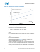
Figure 5-3. Embedded Case Temperature Thermal Profile