
Datasheet


Intel
®
Celeron
®
M Processor Datasheet 29
Package Mechanical Specifications and Pin Information
4 Package Mechanical
Specifications and Pin Information
The processor is available in 478-pin Micro-FCPGA and 479 ball Micro-FCBGA packages.
Different views of the Micro-FCPGA package are shown in Figure 4 through Figure 6. Package
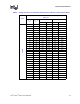
dimensions are shown in Table 14. Different views of the Micro-FCBGA package are shown in
Figure 8 through Figure 10. Package dimensions are shown in Table 15. The Intel
Celeron M
processor die offset is illustrated in Figure 7.
The Micro-FCBGA may have capacitors placed in the area surrounding the die. Because the die-
side capacitors are electrically conductive, and only slightly shorter than the die height, care should
be taken to avoid contacting the capacitors with electrically conductive materials. Doing so may
short the capacitors, and possibly damage the device or render it inactive. The use of an insulating
material between the capacitors and any thermal solution should be considered to prevent capacitor
shorting.
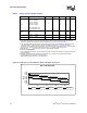
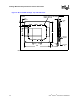
Figure 4. Micro-FCPGA Package Top and Bottom Isometric Views
NOTE: All dimensions in millimeters. Values shown for reference only. Refer to Table 14 for details.
TOP VIEW BOTTOM VIEW
LABEL
PACKAGE KEEPOUT
DIE
CAPACITOR AREA