
Datasheet


Technical Reference
71
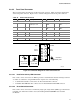
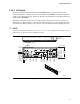
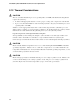
2.8.3.2 Front Panel Connector
This section describes the functions of the front panel connector. Table 38 lists the signal names
of the front panel connector. Figure 24 is a connection diagram for the front panel connector.
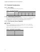
Table 38. Front Panel Connector
Pin Signal In/Out Description Pin Signal In/Out Description
Hard Drive Activity LED Power LED
1 HD_PWR Out Hard disk LED pull-up
(750 Ω) to +5 V
2 HDR_BLNK_
GRN
Out Front panel green
LED
3 HAD# Out Hard disk active LED 4 HDR_BLNK_
YEL
Out Front panel yellow
LED
Reset Switch On/Off Switch
5 Ground Ground 6 FPBUT_IN In Power switch
7 FP_RESET# In Reset switch 8 Ground Ground
Power Not Connected
9 +5 V Power 10 N/C Not connected−
OM15966
8
6
4
2
7
5
3
1
Reset
Switch
+5 V DC
N/C
Power
Switch
9
Hard Drive
Activity LED
Single-colored
Power LED
Dual-colored
Power LED
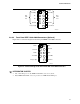
Figure 24. Connection Diagram for Front Panel Connector
2.8.3.2.1 Hard Drive Activity LED Connector
Pins 1 and 3 can be connected to an LED to provide a visual indicator that data is being read from
or written to a hard drive. Proper LED function requires one of the following:
• A Serial ATA hard drive connected to an onboard Serial ATA connector
• A Parallel ATA IDE hard drive connected to an onboard Parallel ATA IDE connector
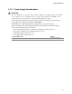
2.8.3.2.2 Reset Switch Connector
Pins 5 and 7 can be connected to a momentary single pole, single throw (SPST) type switch that is
normally open. When the switch is closed, the Desktop Board D865PERL resets and runs
the POST.