
Datasheet


Intel Desktop Board D865PERL Technical Product Specification
70
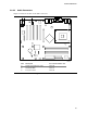
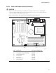
2.8.3 External I/O Connectors
Figure 23 shows the locations of the external I/O connectors.
OM15906
10
2
10
2
1
1
7
7
10
2
1
10
21
7
1
9
8
2
3
1
D
C
B A
Item Description Color For more information see:
A Auxiliary front panel power/sleep/
message-waiting LED
Black Table 37
B Front panel White Table 38
C Front panel USB (2) Black Figure 25
D Front panel IEEE 1394a-2000 (2) (optional) Blue Figure 26
Figure 23. External I/O Connectors
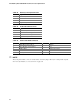
2.8.3.1 Auxiliary Front Panel Power/Sleep/Message-Waiting LED Connector
Pins 1 and 3 of this connector duplicate the signals on pins 2 and 4 of the front panel connector.
Table 37. Auxiliary Front Panel Power/Sleep/Message-Waiting LED Connector
Pin Signal Name In/Out Description
1 HDR_BLNK_GRN Out Front panel green LED
2 Not connected
3 HDR_BLNK_YEL Out Front panel yellow LED