
Datasheet


Intel Desktop Board D865PERL Technical Product Specification
68
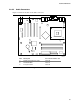
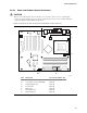
2.8.2.4 Add-in Board and Peripheral Interface Connectors
Figure 22 shows the location of the add-in board and peripheral connectors for the Desktop Board
D865PERL. Note the following considerations for the PCI bus connectors:
• All of the PCI bus connectors are bus master capable.
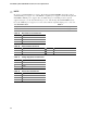
• The SMBus is routed to PCI bus connector 2. This enables PCI bus add-in boards with SMBus
support to access sensor data on the Desktop Board D865PERL. The specific SMBus signals
are as follows:
The SMBus clock line is connected to pin A40
The SMBus data line is connected to pin A41
OM15909
A
JI
KHG
B C D E F
2
40
2
1
1
39
39
1
2
33
34
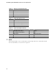
Item Description Item Description
A PCI bus connector 5 G Diskette drive
B PCI bus connector 4 H Primary Parallel ATA IDE [black]
C PCI bus connector 3 I Secondary Parallel ATA IDE [white]
D PCI bus connector 2 J Serial ATA connector 1
E PCI bus connector 1 K Serial ATA connector 0
F AGP
Figure 22. D865PERL Add-in Board and Peripheral Interface Connectors