
Datasheet

Intel Desktop Board D865PERL Technical Product Specification
42
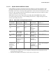
1.12.1.2 Thermal Monitoring
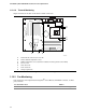
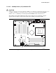
Figure 16 shows the location of the sensors and fan connectors.
OM15901
B
C
A
F EG
D
3
1
3
1
31
13
A Thermal diode, located on processor die
B Remote ambient temperature sensor
C Ambient temperature sensor (internal to hardware monitoring and fan control ASIC)
D Processor fan
E Rear chassis fan
F Front chassis fan
G Voltage regulator fan
Figure 16. Thermal Monitoring
1.12.2 Fan Monitoring
Fan monitoring can be implemented using Intel
®
Active Monitor, LANDesk* software, or third-
party software.
For information about Refer to
The functions of the fan connectors Section 1.13.2.2, page 47