
Datasheet

Product Description
29
is intended for exclusive use with graphical display devices. AGP overcomes certain limitations of
the PCI bus related to handling large amounts of graphics data with the following features:
• Pipelined memory read and write operations that hide memory access latency
• Demultiplexing of address and data on the bus for nearly 100 percent efficiency
#
INTEGRATOR’S NOTES
• AGP 2x operation is not supported.
• Install memory in the DIMM sockets prior to installing the AGP video card to avoid
interference with the memory retention mechanism.
• The AGP connector is keyed for Universal 0.8 V AGP 3.0 specification-compatible cards or
1.5 V AGP 2.0 specification-compatible cards only. Do not attempt to install a legacy 3.3 V
AGP card. The AGP connector is not mechanically compatible with legacy 3.3 V AGP cards.
For information about Refer to
The location of the AGP connector Figure 1, page 14
Obtaining the Accelerated Graphics Port Interface Specification Section 1.4, page 17
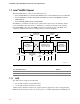
1.7.2 USB
The Desktop Board D865PERL supports up to eight USB 2.0 ports, supports UHCI and EHCI, and
uses UHCI- and EHCI-compatible drivers.
The ICH5/ICH5-R provides the USB controller for all ports. The port arrangement is as follows:
• Two ports are implemented with stacked back panel connectors, adjacent to the PS/2
connectors
• Two ports are implemented with stacked back panel connectors, adjacent to the audio
connectors
• Four ports are routed to two front panel USB connectors
✏
NOTES
• Computer systems that have an unshielded cable attached to a USB port may not meet FCC
Class B requirements, even if no device is attached to the cable. Use shielded cable that meets
the requirements for full-speed devices.
• Native USB 2.0 support has been tested with drivers for Windows 2000 (with Service Pack 3)
and Windows XP (with Service Pack 1) and is not currently supported by any other operating
system. Check Intel’s Desktop Board website for possible driver updates for other operating
systems.
For information about Refer to
The location of the USB connectors on the back panel Figure 19, page 60
The location of the front panel USB connectors Figure 23, page 70
The signal names of the front panel USB connector Figure 25, page 73
The front panel, EHCI, UHCI, and USB specifications Section 1.4, page 17