
Datasheet

Product Description
15
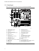
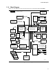
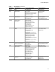
1.1.4 Block Diagram
Figure 2 is a block diagram of the major functional areas of the Desktop Board D865PERL.
Intel 865PE Chipset
Intel 82801EB (ICH5) or
82801ER (ICH5-R)
I/O Controller Hub
Intel 82865PE
Memory Controller
Hub (MCH)
Intel 82802AB
4 Mbit
Firmware Hub
(FWH)
AHA
Bus
System Bus
(400/533/800 MHz)
mPGA478
Processor Socket
Parallel ATA IDE
Connectors (2)
Diskette Drive
Connector
LPC Bus
I/O
Controller
PS/2 Keyboard
PS/2 Mouse
Parallel Port
Serial Port
Parallel ATA
IDE Interface
LPC
Bus
Hardware
Monitoring
and Fan
Control ASIC
OM15984
AD1985
Audio Codec
(Optional)
Mic In
Front Left and Right Out
CD-ROM
Line In
LAN
Connector
10/100
LAN
PLC
(Optional)
CSMA/CD
Unit Interface
AGP
Interface
Universal
0.8/1.5 V
AGP 3.0
Connector
= connector or socket
PCI Bus
SMBus
AC
Link
Back Panel/
Front Panel
USB Ports
USB
Dual-Channel
Memory Bus
SMBus
PCI Slot 1
PCI Slot 2
PCI Slot 3
PCI Slot 4
PCI Slot 5
Center and LFE Out
Rear Left and Right Out
Coaxial S/PDIF
Serial ATA IDE
Connectors (2)
Optical S/PDIF
Serial ATA
IDE Interface
Three
IEEE 1394a-2000
Ports (Optional)
FW323
IEEE 1394a-2000
Controller (Optional)
Channel A
DIMMs (2)
Channel B
DIMMs (2)
Auxiliary Line In
LAN
Connector
Gigabit
LAN
PLC
(Optional)
CSA
Interface
Figure 2. Block Diagram