Intel® Desktop Board D865PERL Technical Product Specification April 2003 Order Number: C31764-001 The Intel® Desktop Board D865PERL may contain design defects or errors known as errata that may cause the product to deviate from published specifications. Current characterized errata are documented in the Intel Desktop Board D865PERL Specification Update.
Revision History Revision -001 Revision History First release of the Specification. Date Intel Desktop Board D865PERL Technical Product April 2003 This product specification applies to only the standard Intel Desktop Board D865PERL with BIOS identifier RL86510A.86A. Changes to this specification will be published in the Intel Desktop Board D865PERL Specification Update before being incorporated into a revision of this document.
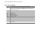
Preface This Technical Product Specification (TPS) specifies the Intel® Desktop Board D865PERL layout, components, connectors, power and environmental requirements, and BIOS. The TPS describes the standard product and available manufacturing options. Intended Audience The TPS is intended to provide detailed, technical information about the Desktop Board and its components to the vendors, system integrators, and other engineers and technicians who need this level of information.
Intel Desktop Board D865PERL Technical Product Specification Other Common Notation iv # Used after a signal name to identify an active-low signal (such as USBP0#) (NxnX) When used in the description of a component, N indicates component type, xn are the relative coordinates of its location on the Desktop Board D865PERL, and X is the instance of the particular part at that general location. For example, J5J1 is a connector, located at 5J. It is the first connector in the 5J area.
Contents 1 Product Description 1.1 1.2 1.3 1.4 1.5 1.6 1.7 1.8 1.9 1.10 1.11 1.12 1.13 Overview ....................................................................................................................12 1.1.1 Feature Summary ........................................................................................12 1.1.2 Manufacturing Options .................................................................................13 1.1.3 Board Layout..............................................
Intel Desktop Board D865PERL Technical Product Specification 2 Technical Reference 2.1 2.2 2.3 2.4 2.5 2.6 2.7 2.8 2.9 2.10 2.11 2.12 2.13 2.14 2.15 Introduction.................................................................................................................51 Memory Resources ....................................................................................................51 2.2.1 Addressable Memory ...................................................................................
Contents 3.7 3.8 Recovering BIOS Data ...............................................................................................91 Boot Options...............................................................................................................91 3.8.1 CD-ROM Boot ..............................................................................................91 3.8.2 Network Boot................................................................................................92 3.8.
Intel Desktop Board D865PERL Technical Product Specification Figures 1. 2. 3. 4. 5. 6. 7. 8. 9. 10. 11. 12. 13. 14. 15. 16. 17. 18. 19. 20. 21. 22. 23. 24. 25. 26. 27. 28. 29. 30. Desktop Board D865PERL Components ....................................................................14 Block Diagram ............................................................................................................15 Memory Channel Configuration .......................................................................
Contents 14. 15. 16. 17. 18. 19. 20. 21. 22. 23. 24. 25. 26. 27. 28. 29. 30. 31. 32. 33. 34. 35. 36. 37. 38. 39. 40. 41. 42. 43. 44. 45. 46. 47. 48. 49. 50. 51. 52. 53. 54. 55. 56. 57. 58. 59. 60. 61. DMA Channels ...........................................................................................................53 I/O Map ......................................................................................................................54 PCI Configuration Space Map .............................
Intel Desktop Board D865PERL Technical Product Specification 62. 63. 64. 65. 66. 67. 68. 69. 70. 71. 72. 73. 74. 75. 76. 77. 78. 79. 80. 81. 82. 83. 84. 85. 86. x Floppy Configuration Submenu ................................................................................107 Event Log Configuration Submenu ...........................................................................108 Video Configuration Submenu ..................................................................................
1 Product Description What This Chapter Contains 1.1 1.2 1.3 1.4 1.5 1.6 1.7 1.8 1.9 1.10 1.11 1.12 1.13 Overview ....................................................................................................................12 Online Support ...........................................................................................................16 Operating System Support .........................................................................................16 Design Specifications ..............
Intel Desktop Board D865PERL Technical Product Specification 1.1 Overview 1.1.1 Feature Summary Table 1 summarizes the major features of the Intel® Desktop Board D865PERL. Table 1. Feature Summary Form Factor ATX (12.0 inches by 9.6 inches [304.80 millimeters by 243.
Product Description Table 1. Feature Summary (continued) • Intel/AMI BIOS (resident in the Intel 82802AB FWH) BIOS • Support for Advanced Configuration and Power Interface (ACPI), Plug and Play, and SMBIOS Instantly Available PC Technology • Support for PCI Local Bus Specification Revision 2.2 • Suspend to RAM support • Wake on PCI, RS-232, front panel, PS/2 devices, and USB ports For information about Refer to The Desktop Board D865PERL’s compliance level with ACPI, Plug and Play, and SMBIOS.
Intel Desktop Board D865PERL Technical Product Specification 1.1.3 Board Layout Figure 1 shows the location of the major components on the Desktop Board D865PERL.
Product Description 1.1.4 Block Diagram Figure 2 is a block diagram of the major functional areas of the Desktop Board D865PERL. = connector or socket Back Panel/ Front Panel USB Ports USB Parallel ATA IDE Connectors (2) mPGA478 Processor Socket Serial Port Parallel ATA IDE Interface Parallel Port LPC Bus I/O Controller PS/2 Mouse PS/2 Keyboard System Bus (400/533/800 MHz) Diskette Drive Connector LPC Bus AGP Interface Universal 0.8/1.5 V AGP 3.
Intel Desktop Board D865PERL Technical Product Specification 1.2 Online Support To find information about… Visit this World Wide Web site: The Desktop Board D865PERL, look under “Desktop Board Products” or “Desktop Board Support” http://www.intel.com/design/motherbd Available configurations for the Desktop Board D865PERL http://developer.intel.com/design/motherbd/rl/rl_available.htm Processor data sheets http://www.intel.com/design/litcentr http://support.intel.
Product Description 1.4 Design Specifications Table 3 lists the specifications applicable to the Desktop Board D865PERL. Table 3. Specifications Reference Name Specification Title Version, Revision Date, and Ownership The information is available from… 1394 IEEE Std 1394-1995, IEEE Standard for a High Performance Serial Bus November 8, 2001, Institute of Electrical and Electronic Engineers. http://standards.ieee.org/ catalog/olis/busarch.
Intel Desktop Board D865PERL Technical Product Specification Table 3. Specifications (continued) Reference Name Specification Title Version, Revision Date and Ownership The information is available from… BIS Boot Integrity Services (BIS) Application Programming Interface (API) Version 1.0, August 4, 1999, Intel Corporation. http://www.intel.com/labs/ manage/wfm/wfmspecs.htm DDR SDRAM Double Data Rate (DDR) SDRAM Specification Version 2.0, May 2002, JEDEC Solid State Technology Association.
Product Description Table 3. Specifications (continued) Reference Name Specification Title Version, Revision Date and Ownership The information is available from… Plug and Play Plug and Play BIOS Specification Version 1.0a, May 5, 1994, Compaq Computer Corporation, Phoenix Technologies Limited, and Intel Corporation. http://www.microsoft.com/ hwdev/tech/PnP/ default.asp PXE Preboot Execution Environment Version 2.1, September 20, 1999, Intel Corporation. ftp://download.intel.
Intel Desktop Board D865PERL Technical Product Specification 1.5 Processor ✏ NOTE Refer to Thermal Considerations (Section 2.12, page 80) for important information when using an Intel Pentium 4 processor operating above 2.80 GHz with this Intel desktop board.
Product Description 1.6 System Memory 1.6.1 Memory Features The Desktop Board D865PERL has four DIMM sockets and supports the following memory features: • • 2.5 V (only) 184-pin DDR SDRAM DIMMs with gold-plated contacts Unbuffered, single-sided or double-sided DIMMs with the following restriction: Double-sided DIMMS with x16 organization are not supported. • • • • • 4 GB maximum total system memory. Refer to Section 2.2.1 on page 51 for information on the total amount of addressable memory.
Intel Desktop Board D865PERL Technical Product Specification Table 5 lists the supported DIMM configurations. Table 5.
Product Description 1.6.2 Memory Configurations The Intel 82865PE MCH component provides two features for enhancing memory throughput: • • Dual Channel memory interface. The board has two memory channels, each with two DIMM sockets, as shown in Figure 3 Dynamic Addressing Mode. Dynamic mode minimizes overhead by reducing memory accesses Table 6 summarizes the characteristics of Dual and Single Channel configurations with and without the use of Dynamic Mode. Table 6.
Intel Desktop Board D865PERL Technical Product Specification Dual Channel Configuration with Dynamic Mode (All DIMMs matched) Channel A - DIMM 0 Channel B - DIMM 0 Example 1 Channel A - DIMM 1 Intel 82865PE MCH Channel A - DIMM 0 Channel B - DIMM 1 Channel B - DIMM 0 Example 2 Channel A - DIMM 1 Intel 82865PE MCH Channel B - DIMM 1 OM15985 Throughput Level Configuration Characteristics Highest Dual Channel with Dynamic Mode All DIMMs matched Dual Channel without Dynamic Mode • DIMMs matc
Product Description Dual Channel Configuration without Dynamic Mode - DIMMs not matched within channel - DIMMs match Channel A to Channel B Channel A - DIMM 0 Channel A - DIMM 1 Channel B - DIMM 0 Intel 82865PE MCH Channel B - DIMM 1 OM15986 Throughput Level Configuration Characteristics Highest Dual Channel with Dynamic Mode All DIMMs matched Dual Channel without Dynamic Mode • DIMMs matched from Channel A to Channel B Single Channel with Dynamic Mode Single DIMM or DIMMs matched within a
Intel Desktop Board D865PERL Technical Product Specification Single Channel Configuration with Dynamic Mode (Single DIMM or DIMMs matched within Channel) Channel A - DIMM 0 Channel B - DIMM 0 Example 1 Channel A - DIMM 1 Intel 82865PE MCH Channel A - DIMM 0 Channel B - DIMM 1 Channel B - DIMM 0 Example 2 Channel A - DIMM 1 Intel 82865PE MCH Channel B - DIMM 1 OM15987 Throughput Level Configuration Characteristics Highest Dual Channel with Dynamic Mode All DIMMs matched Dual Channel withou
Product Description Channel A - DIMM 0 Channel B - DIMM 0 Example 1 Channel A - DIMM 1 Intel 82865PE MCH Channel A - DIMM 0 Channel B - DIMM 1 Channel B - DIMM 0 Example 2 Channel A - DIMM 1 Intel 82865PE MCH Channel B - DIMM 1 OM15988 Throughput Level Highest Configuration Characteristics Dual Channel with Dynamic Mode All DIMMs matched Dual Channel without Dynamic Mode • DIMMs matched from Channel A to Channel B Single Channel with Dynamic Mode Single DIMM or DIMMs matched within a cha
Intel Desktop Board D865PERL Technical Product Specification 1.7 Intel® 865PE Chipset The Intel 865PE chipset consists of the following devices: • • • Intel 82865PE Memory Controller Hub (MCH) with Accelerated Hub Architecture (AHA) bus Intel 82801EB I/O Controller Hub (ICH5) with AHA bus or Intel 82801ER I/O Controller HUB (ICH5-R) Intel 82802AB (4 Mbit) Firmware Hub (FWH) The MCH is a centralized controller for the system bus, the memory bus, the AGP bus, and the Accelerated Hub Architecture interface.
Product Description is intended for exclusive use with graphical display devices. AGP overcomes certain limitations of the PCI bus related to handling large amounts of graphics data with the following features: • • # Pipelined memory read and write operations that hide memory access latency Demultiplexing of address and data on the bus for nearly 100 percent efficiency INTEGRATOR’S NOTES • • • AGP 2x operation is not supported.
Intel Desktop Board D865PERL Technical Product Specification 1.7.3 IDE Support The board provides four IDE interface connectors: • • 1.7.3.1 Two Parallel ATA IDE connectors, which support a total of four devices (two per connector) Two Serial ATA IDE connectors, which support one drive per connector Parallel ATA IDE Interfaces The ICH5’s Parallel ATA IDE controller has two independent bus-mastering Parallel ATA IDE interfaces that can be independently enabled.
Product Description IDE I/O and IRQ resources are assigned (IRQ 14 and 15). In Native mode, standard PCI resource steering is used. Native mode is the preferred mode for configurations using the Windows XP and Windows 2000 operating systems. ✏ NOTE Many Serial ATA drives use new low-voltage power connectors and require adaptors or power supplies equipped with low-voltage power connectors. For information about Refer to Serial ATA http://www.serialata.org 1.7.3.
Intel Desktop Board D865PERL Technical Product Specification ✏ NOTE If the battery and AC power fail, custom defaults, if previously saved, will be loaded into CMOS RAM at power-on. 1.7.5 Intel® 82802AB Firmware Hub (FWH) The 4 Mbit FWH provides the following: • • System BIOS program Logic that enables protection for storing and updating of platform information 1.
Product Description 1.8.3 Diskette Drive Controller The I/O controller supports one diskette drive. Use the BIOS Setup program to configure the diskette drive interface. For information about Refer to The location of the diskette drive connector Figure 22, page 68 The supported diskette drive capacities and sizes Table 62, page 107 1.8.4 Keyboard and Mouse Interface The PS/2 keyboard and mouse connectors are located on the back panel.
Intel Desktop Board D865PERL Technical Product Specification 1.10 Audio Subsystem The Desktop Board D865PERL includes one of the following: • • 6-channel audio subsystem based on the Analog Devices AD1985 codec (described on page 34) Flex 6 audio subsystem based on the Analog Devices AD1985 codec (described on page 36) Both audio subsystems feature: • • • 1.10.
Product Description Figure 9 shows the back panel audio connectors for the 6-channel audio subsystem. Rear Channel Left and Right Out Coaxial S/PDIF (RCA) Optical S/PDIF (TOSlink) Line In (Light Blue) Front Channel Left and Right Out (Lime Green) Mic In (Pink) Center Channel and LFE (Subwoofer) Out OM15975 Figure 9. Back Panel Connectors for 6-Channel Audio Subsystem Figure 10 is a block diagram of the 6-channel audio subsystem.
Intel Desktop Board D865PERL Technical Product Specification 1.10.
Product Description Connect to S/PDIF output on Back Panel RCA Jack Left Channel (White, if colored) Connect to 5.1 speaker system or an S/PDIF decoder 1/8-inch Stereo Phone Plug OM16108 Figure 12. Adapter for S/PDIF Back Panel Connector Figure 13 is a block diagram of the Flex 6 audio subsystem.
Intel Desktop Board D865PERL Technical Product Specification 1.10.3.2 Front Panel Audio Connector A 2 x 5-pin connector provides mic in and line out signals for front panel audio connectors. ✏ For information about Refer to The location of the connector Section 2.8.3, page 70 The signal names of the front panel audio connector Table 28, page 64 NOTE The front panel audio connector is alternately used as a jumper block for routing audio signals. Refer to Section 2.9.
Product Description 1.11 LAN Subsystem The LAN subsystem consists of the following: • Physical layer interface device.
Intel Desktop Board D865PERL Technical Product Specification Table 7 describes the LED states when the board is powered up and the 10/100 Mbits/sec LAN subsystem is operating. Table 7. LED Color Green Yellow 1.11.2 LAN Connector LED States LED State Condition Off 10 Mbits/sec data rate is selected. On 100 Mbits/sec data rate is selected. Off LAN link is not established. On (steady state) LAN link is established.
Product Description Table 8. LED LAN Connector LED States Color Left Green Right Green Orange 1.11.3 LED State Condition Off LAN link is not established. On (steady state) LAN link is established. On (brighter and pulsing) The computer is communicating with another computer on the LAN. Off 10 Mbit/sec data rate is selected. On 100 Mbit/sec data rate is selected. On 1000 Mbit/sec data rate is selected.
Intel Desktop Board D865PERL Technical Product Specification 1.12.1.2 Thermal Monitoring Figure 16 shows the location of the sensors and fan connectors. 3 1 1 3 A B C D 1 3 1 3 G F E OM15901 A B C D E F G Thermal diode, located on processor die Remote ambient temperature sensor Ambient temperature sensor (internal to hardware monitoring and fan control ASIC) Processor fan Rear chassis fan Front chassis fan Voltage regulator fan Figure 16. Thermal Monitoring 1.12.
Product Description 1.12.3 Chassis Intrusion and Detection The boards support a chassis security feature that detects if the chassis cover has been removed. The security feature uses a mechanical switch on the chassis that attaches to the chassis intrusion connector. When the chassis cover is removed, the mechanical switch is in the closed position.
Intel Desktop Board D865PERL Technical Product Specification 1.13.1 ACPI ACPI gives the operating system direct control over the power management and Plug and Play functions of a computer. The use of ACPI with the Desktop Board D865PERL requires an operating system that provides full ACPI support.
Product Description 1.13.1.1 System States and Power States Under ACPI, the operating system directs all system and device power state transitions. The operating system puts devices in and out of low-power states based on user preferences and knowledge of how devices are being used by applications. Devices that are not being used can be turned off. The operating system uses information from applications and user settings to put the system as a whole into a low-power state.
Intel Desktop Board D865PERL Technical Product Specification 1.13.1.2 Wake-up Devices and Events Table 11 lists the devices or specific events that can wake the computer from specific states. Table 11.
Product Description ✏ NOTE The use of Resume on Ring and Wake from USB technologies from an ACPI state requires an operating system that provides full ACPI support. 1.13.2.1 Power Connector ATX12V-compliant power supplies can turn off the system power through system control. When an ACPI-enabled system receives the correct command, the power supply removes all non-standby voltages.
Intel Desktop Board D865PERL Technical Product Specification For information about: Refer to: The location of the fan connectors The signal names of the fan connectors The location of the fan connectors and sensors for thermal monitoring Figure 21, page 65 Pages 66 and 67 Figure 16, page 42 1.13.2.3 LAN Wake Capabilities CAUTION For LAN wake capabilities, the +5 V standby line for the power supply must be capable of providing adequate +5 V standby current.
Product Description 1.13.2.5 Standby Power (+5 V) Indicator LED CAUTION If AC power has been switched off and the standby power indicator is still lit, disconnect the power cord before installing or removing any devices connected to the Desktop Board D865PERL. Failure to do so could damage the Desktop Board D865PERL and any attached devices. The standby power indicator LED shows that power is still present even when the computer appears to be off.
Intel Desktop Board D865PERL Technical Product Specification 1.13.2.6 Resume on Ring The operation of Resume on Ring can be summarized as follows: • • • 1.13.2.7 Resumes operation from ACPI S1 or S3 states Detects incoming call similarly for external and internal modems Requires modem interrupt be unmasked for correct operation Wake from USB USB bus activity wakes the computer from an ACPI S1 or S3 state. ✏ NOTE Wake from USB requires the use of a USB peripheral that supports Wake from USB. 1.13.
2 Technical Reference What This Chapter Contains 2.1 2.2 2.3 2.4 2.5 2.6 2.7 2.8 2.9 2.10 2.11 2.12 2.13 2.14 Introduction.................................................................................................................51 Memory Resources ....................................................................................................51 DMA Channels ...........................................................................................................53 Fixed I/O Map.................
Intel Desktop Board D865PERL Technical Product Specification memory, AGP aperture set for 256 MB, and the PCI cards are requesting 200 MB of system address space.
Technical Reference 2.2.2 Memory Map Table 13 lists the system memory map. Table 13. System Memory Map Address Range (decimal) Address Range (hex) Size Description 1024 K - 4194304 K 100000 - FFFFFFFF 4095 MB Extended memory 960 K - 1024 K F0000 - FFFFF 64 KB Runtime BIOS 896 K - 960 K E0000 - EFFFF 64 KB Reserved 800 K - 896 K C8000 - DFFFF 96 KB Potential available high DOS memory (open to the PCI bus). Dependent on video adapter used.
Intel Desktop Board D865PERL Technical Product Specification 2.4 Fixed I/O Map Table 15. I/O Map Address (hex) Size Description 0000 - 00FF 256 bytes 0170 - 0177 01F0 - 01F7 8 bytes 8 bytes Used by the Desktop Board D865PERL.
Technical Reference 2.5 PCI Configuration Space Map Table 16.
Intel Desktop Board D865PERL Technical Product Specification 2.6 Interrupts The interrupts can be routed through either the Programmable Interrupt Controller (PIC) or the Advanced Programmable Interrupt Controller (APIC) portion of the ICH5 component. The PIC is supported in Windows 98 SE and Windows ME, and uses the first 16 interrupts. The APIC is supported in Windows 2000 and Windows XP, and supports a total of 24 interrupts. Table 17.
Technical Reference 2.7 PCI Interrupt Routing Map This section describes interrupt sharing and how the interrupt signals are connected between the PCI bus connectors and onboard PCI devices. The PCI specification specifies how interrupts can be shared between devices attached to the PCI bus. In most cases, the small amount of latency added by interrupt sharing does not affect the operation or throughput of the devices.
Intel Desktop Board D865PERL Technical Product Specification Table 18. PCI Interrupt Routing Map ICH5 PIRQ Signal Name PCI Interrupt Source PIRQA PIRQB AGP connector INTA INTB PIRQC PIRQD PIRQE PIRQF PIRQG PIRQH ICH5 USB UHCI controller 1 INTA SMBus controller INTB ICH5 USB UHCI controller 2 INTB AC ’97 ICH5 Audio INTB ICH5 LAN INTA ICH5 USB UHCI controller 3 INTC ICH5 USB UHCI controller 4 INTA INTD ICH5 USB 2.
Technical Reference 2.8 Connectors CAUTION On the Desktop Board D865PERL, only the following connectors have overcurrent protection: • Back panel USB, IEEE 1394a-2000, and PS/2 • Front panel USB and IEEE 1394a-2000 The other internal connectors of the Desktop Board D865PERL are not overcurrent protected and should connect only to devices inside the computer’s chassis, such as fans and internal peripherals. Do not use these connectors to power devices external to the computer’s chassis.
Intel Desktop Board D865PERL Technical Product Specification 2.8.1 Back Panel Connectors Figure 19 shows the location of the back panel connectors. The back panel connectors are color-coded in compliance with PC 99 recommendations. The figure legend below lists the colors used.
Technical Reference Table 19. Coaxial S/PDIF Connector (Optional) Pin Signal Name Tip S/PDIF Sleeve Ground Table 20. Optical S/PDIF Connector (Optional) Location Signal Name Tunnel S/PDIF Table 21. Pin Audio Rear Left and Right Out Connector (Optional) Signal Name Tip Rear left out Ring Rear right out Sleeve Ground Table 22. Pin Audio Center and LFE Out Connector (Optional) Signal Name Tip Center out Ring LFE out Sleeve Ground Table 23.
Intel Desktop Board D865PERL Technical Product Specification 2.8.2 Internal I/O Connectors The internal I/O connectors are divided into the following functional groups: • • • 2.8.2.
Technical Reference 2.8.2.2 Audio Connectors Figure 21 shows the location of the audio connectors. A B 1 1 4 C 1 2 9 10 4 OM15900 Item Description For more information see: A ATAPI-style auxiliary line input Table 26 B ATAPI CD-ROM Table 27 C Front panel audio Table 28 Figure 20.
Intel Desktop Board D865PERL Technical Product Specification Table 26. Pin Signal Name 1 Left auxiliary line in 2 Ground 3 Ground 4 Right auxiliary line in Table 27. ATAPI CD-ROM Connector Pin Signal Name 1 Left audio input from CD-ROM 2 CD audio differential ground 3 CD audio differential ground 4 Right audio input from CD-ROM Table 28.
Technical Reference 2.8.2.3 Power and Hardware Control Connectors CAUTION The processor fan must be connected to the processor fan connector, not to a chassis fan connector. Connecting the processor fan to a chassis fan connector may result in onboard component damage that will halt fan operation. Figure 21 shows the location of the power and hardware control connectors.
Intel Desktop Board D865PERL Technical Product Specification ✏ NOTE Do not use a standard ATX power supply. The Desktop Board D865PERL will not boot with a standard ATX power supply. Use only ATX12V-compliant power supplies with the Desktop Board D865PERL. ATX12V power supplies have an additional power lead that provides required supplemental power for the Intel Pentium 4 processor.
Technical Reference Table 33. Main Power Connector Pin Signal Name Pin Signal Name 1 +3.3 V 11 +3.3 V 2 +3.3 V 12 -12 V 3 Ground 13 Ground 4 +5 V 14 PS-ON# (power supply remote on/off) 5 Ground 15 Ground 6 +5 V 16 Ground 7 Ground 17 Ground 8 PWRGD (Power Good) 18 Not connected 9 +5 V (Standby) 19 +5 V 10 +12 V 20 +5 V Table 34. Front Chassis Fan Connector Pin Signal Name 1 Control 2 +12 V 3 TACH Table 35.
Intel Desktop Board D865PERL Technical Product Specification 2.8.2.4 Add-in Board and Peripheral Interface Connectors Figure 22 shows the location of the add-in board and peripheral connectors for the Desktop Board D865PERL. Note the following considerations for the PCI bus connectors: • • All of the PCI bus connectors are bus master capable. The SMBus is routed to PCI bus connector 2. This enables PCI bus add-in boards with SMBus support to access sensor data on the Desktop Board D865PERL.
Technical Reference ✏ NOTE The AGP connector is keyed for universal 0.8 V AGP 3.0 cards or 1.5 V AGP 2.0 cards only. Do not attempt to install a legacy 3.3 V AGP card. The AGP connector is not mechanically compatible with legacy 3.3 V AGP cards Table 36.
Intel Desktop Board D865PERL Technical Product Specification 2.8.3 External I/O Connectors Figure 23 shows the locations of the external I/O connectors. 1 7 D 1 7 1 2 10 2 10 2 1 10 2 7 10 C 8 2 B 9 1 1 3 A OM15906 Item Description Color For more information see: A Auxiliary front panel power/sleep/ message-waiting LED Front panel Front panel USB (2) Front panel IEEE 1394a-2000 (2) (optional) Black Table 37 White Black Blue Table 38 Figure 25 Figure 26 B C D Figure 23.
Technical Reference 2.8.3.2 Front Panel Connector This section describes the functions of the front panel connector. Table 38 lists the signal names of the front panel connector. Figure 24 is a connection diagram for the front panel connector. Table 38.
Intel Desktop Board D865PERL Technical Product Specification 2.8.3.2.3 Power/Sleep/Message Waiting LED Connector Pins 2 and 4 can be connected to a one- or two-color LED. Table 39 shows the possible states for a one-color LED. Table 40 shows the possible states for a two-color LED. Table 39. LED State Description Off Power off/sleeping Steady Green Running Blinking Green Running/message waiting Table 40.
Technical Reference Power (+5 V DC) 1 2 Power (+5 V DC) D− 3 4 D− D+ 5 6 D+ Ground 7 8 Ground 10 No Connect One USB Port Key (no pin) One USB Port OM15963 Figure 25. Connection Diagram for Front Panel USB Connectors 2.8.3.4 Front Panel IEEE 1394a-2000 Connectors (Optional) Figure 26 is a connection diagram for the front panel IEEE 1394a-2000 connectors. TPA+ 1 2 TPA− Ground 3 4 Ground TPB+ 5 6 TPB− 7 8 +12 V DC 10 Ground +12 V DC Key (no pin) OM16107 Figure 26.
Intel Desktop Board D865PERL Technical Product Specification 2.9 Jumper Blocks CAUTION Do not move any jumpers with the power on. Always turn off the power and unplug the power cord from the computer before changing a jumper setting. Otherwise, the Desktop Board D865PERL could be damaged. Figure 27 shows the location of the jumper blocks on the Desktop Board D865PERL.
Technical Reference Table 41 describes the two configurations of this connector/jumper block. Table 41. Front Panel Audio Connector or Jumper Block Jumper Setting 1 2 3 4 5 6 1 and 2 3 and 4 5 and 6 10 9 and 10 Configuration Front out signals if 6-channel audio (line out signals if 2-channel audio) are routed to the back panel line out connector. The back panel audio line out connector is shown in Figure 19 on page 60.
Intel Desktop Board D865PERL Technical Product Specification 2.10 Mechanical Considerations 2.10.1 D865PERL Form Factor The Desktop Board D865PERL is designed to fit into an ATX-form-factor chassis. In Figure 28, dimensions are given in inches [millimeters]. The outer dimensions of the board are 12.0 inches by 9.6 inches [304.80 millimeters by 243.84 millimeters]. Location of the I/O connectors and mounting holes are in compliance with the ATX specification (see Section 1.4). 1.800 [45.72] 6.500 [165.
Technical Reference 2.10.2 I/O Shield The back panel I/O shield for Desktop Board D865PERL must meet specific dimension and material requirements. Systems based on the Desktop Board D865PERL need the back panel I/O shield to pass certification testing. Figure 29 show the critical dimensions of the I/O shield for the Desktop Board D865PERL. The figure indicates the position of each cutout and gives dimensions in inches to a tolerance of ±0.02 inches.
Intel Desktop Board D865PERL Technical Product Specification 2.11 Electrical Considerations 2.11.1 DC Loading Table 43 lists the DC loading characteristics of the board. Table 43. DC Loading Characteristics DC Current at: Mode DC Power +3.3 V +5 V +12 V -12 V +5 VSB Minimum loading 196 W 6A 11 A 9A 0.03 A 0.80 A Maximum loading 330 W 12 A 15 A 16 A 0.10 A 1.60 A 2.11.
Technical Reference 2.11.4 Power Supply Considerations CAUTION The +5 V standby line for the power supply must be capable of providing adequate +5 V standby current. Failure to do so can damage the power supply. The total amount of standby current required depends on the wake devices supported and manufacturing options. System integrators should refer to the power usage values listed in Table 43 when selecting a power supply for use with the Desktop Board D865PERL.
Intel Desktop Board D865PERL Technical Product Specification 2.12 Thermal Considerations CAUTION The use of an Intel Pentium 4 processor operating above 2.80 GHz with this Intel desktop board requires the following: • A chassis with appropriate airflow to ensure proper cooling of the components on the board • A processor fan heatsink that meets the thermal performance targets for Pentium 4 processors operating above 2.
Technical Reference Figure 30 shows the locations of the localized high temperature zones. A B C D OM15903 Item Description A B C D Processor voltage regulator area Processor Intel 82865PE MCH Intel 82801EB ICH5 or 82801ER ICH5-R Figure 30. Localized High Temperature Zones Table 45 provides maximum case temperatures for components on the Desktop Board D865PERL that are sensitive to thermal changes. The operating temperature, current load, or operating frequency could affect case temperatures.
Intel Desktop Board D865PERL Technical Product Specification 2.13 Reliability The Mean Time Between Failures (MTBF) prediction is calculated using component and subassembly random failure rates. The calculation is based on the Bellcore Reliability Prediction Procedure, TR-NWT-000332, Issue 4, September 1991. The MTBF prediction is used to estimate repair rates and spare parts requirements. The MTBF data is calculated from predicted data at 55 ºC.
Technical Reference 2.15 Regulatory Compliance This section describes the Desktop Boards’ compliance with U.S. and international safety and electromagnetic compatibility (EMC) regulations. 2.15.1 Safety Regulations Table 47 lists the safety regulations the Desktop Board D865PERL complies with when correctly installed in a compatible host system. Table 47. Safety Regulations Regulation Title UL 60950 3rd ed.,2000/CSA C22.2 No.
Intel Desktop Board D865PERL Technical Product Specification 2.15.2.1 FCC Compliance Statement (USA) Product Type: D865PERL Desktop Board This device complies with Part 15 of the FCC Rules. Operation is subject to the following two conditions: (1) This device may not cause harmful interference, and (2) this device must accept any interference received, including interference that may cause undesired operation.
Technical Reference 2.15.4.1 Disposal Considerations This product contains the following materials that may be regulated upon disposal: lead solder on the printed wiring board assembly. 2.15.4.2 Recycling Considerations Intel encourages its customers to recycle its products and their components (e.g., batteries, circuit boards, plastic enclosures, etc.) whenever possible. In the U.S., a list of recyclers in your area can be found at: http://www.eiae.
Intel Desktop Board D865PERL Technical Product Specification 86
3 Overview of BIOS Features What This Chapter Contains 3.1 3.2 3.3 3.4 3.5 3.6 3.7 3.8 3.9 3.10 Introduction.................................................................................................................87 BIOS Flash Memory Organization ..............................................................................87 Resource Configuration ..............................................................................................88 System Management BIOS (SMBIOS) .......................
Intel Desktop Board D865PERL Technical Product Specification 3.3 Resource Configuration 3.3.1 PCI Autoconfiguration The BIOS can automatically configure PCI devices. PCI devices may be onboard or add-in cards. Autoconfiguration lets a user insert or remove PCI cards without having to configure the system. When a user turns on the system after adding a PCI card, the BIOS automatically configures interrupts, the I/O space, and other system resources.
Overview of BIOS Features • • Resource data, such as memory size, cache size, and processor speed Dynamic data, such as event detection and logging Non-Plug and Play operating systems require an additional interface for obtaining the SMBIOS information. The BIOS supports an SMBIOS table interface for such operating systems. Using this support, an SMBIOS service-level application running on a non-Plug and Play operating system can obtain the SMBIOS information.
Intel Desktop Board D865PERL Technical Product Specification Both utilities support the following BIOS maintenance functions: • • • • • • ✏ Verifying that the updated BIOS matches the target system to prevent accidentally installing an incompatible BIOS. Updating both the BIOS boot block and the main BIOS. This process is fault tolerant to prevent boot block corruption. Updating the BIOS boot block separately. Changing the language section of the BIOS.
Overview of BIOS Features 3.7 Recovering BIOS Data Some types of failure can destroy the BIOS. For example, the data can be lost if a power outage occurs while the BIOS is being updated in flash memory. The BIOS can be recovered from a 1.44 MB diskette or CD-ROM using the BIOS recovery mode. When recovering the BIOS, be aware of the following: • • • • Because of the small amount of code available in the non-erasable boot block area, there is no video support.
Intel Desktop Board D865PERL Technical Product Specification 3.8.2 Network Boot The network can be selected as a boot device. This selection allows booting from the onboard LAN or from a network add-in card with a remote boot ROM installed. Pressing the key during POST automatically forces booting from the LAN. To use this key during POST, the User Access Level in the BIOS Setup program’s Security menu must be set to Full.
Overview of BIOS Features 3.9 Fast Booting Systems with Intel® Rapid BIOS Boot These factors affect system boot speed: • • 3.9.1 Selecting and configuring peripherals properly Using an optimized BIOS, such as the Intel® Rapid BIOS Peripheral Selection and Configuration The following techniques help improve system boot speed: • • • • 3.9.2 Choose a hard drive with parameters such as “power-up to data ready” less than eight seconds, that minimize hard drive startup delays.
Intel Desktop Board D865PERL Technical Product Specification 3.10 BIOS Security Features The BIOS includes security features that restrict access to the BIOS Setup program and who can boot the computer. A supervisor password and a user password can be set for the BIOS Setup program and for booting the computer, with the following restrictions: • • • • • The supervisor password gives unrestricted access to view and change all the Setup options in the BIOS Setup program. This is the supervisor mode.
4 BIOS Setup Program What This Chapter Contains 4.1 4.2 4.3 4.4 4.5 4.6 4.7 4.8 Introduction.................................................................................................................95 Maintenance Menu .....................................................................................................96 Main Menu..................................................................................................................97 Advanced Menu...........................................
Intel Desktop Board D865PERL Technical Product Specification Table 53 lists the function keys available for menu screens. Table 53.
BIOS Setup Program 4.3 Main Menu To access this menu, select Main on the menu bar at the top of the screen. Maintenance Main Advanced Security Power Boot Exit Table 55 describes the Main menu. This menu reports processor and memory information and is for configuring the system date and system time. Table 55. Main Menu Feature Options Description BIOS Version No options Displays the version of the BIOS. Processor Type No options Displays processor type.
Intel Desktop Board D865PERL Technical Product Specification 4.4 Advanced Menu To access this menu, select Advanced on the menu bar at the top of the screen. Maintenance Main Advanced Security Power Boot Exit PCI Configuration Boot Configuration Peripheral Configuration Drive Configuration Floppy Configuration Event Log Configuration Video Configuration USB Configuration Chipset Configuration Fan Control Configuration Hardware Monitoring Table 56 describes the Advanced Menu.
BIOS Setup Program 4.4.1 PCI Configuration Submenu To access this submenu, select Advanced on the menu bar and then PCI Configuration.
Intel Desktop Board D865PERL Technical Product Specification Table 57. PCI Configuration Submenu (continued) Feature Options Description PCI Slot5 IRQ Priority • Auto (default) Allows selection of IRQ priority for PCI bus connector 5. (Note) • 3 • 5 • 9 • 10 • 11 Note: Additional interrupts may be available if certain onboard devices (such as the serial and parallel ports) are disabled. 4.4.
BIOS Setup Program 4.4.3 Peripheral Configuration Submenu To access this submenu, select Advanced on the menu bar and then Peripheral Configuration.
Intel Desktop Board D865PERL Technical Product Specification Table 59. Peripheral Configuration Submenu (continued) Feature Options Description Parallel port • Disabled Configures the parallel port. • Enabled Auto assigns LPT1 the address 378h and the interrupt IRQ7. • Auto (default) An * (asterisk) displayed next to an address indicates a conflict with another device. Mode • Output Only • Bi-directional (default) Selects the mode for the parallel port.
BIOS Setup Program 4.4.4 Drive Configuration Submenu To access this submenu, select Advanced on the menu bar and then Drive Configuration. Maintenance Main Advanced Security Power Boot Exit PCI Configuration Boot Configuration Peripheral Configuration Drive Configuration Floppy Configuration Event Log Configuration Video Configuration USB Configuration Chipset Configuration Fan Control Configuration Hardware Monitoring The menu represented in Table 60 is used to configure IDE device options.
Intel Desktop Board D865PERL Technical Product Specification Table 60. Drive Configuration Submenu (continued) Feature Options Description Soft RAID Support • Disabled (default) Enables/disables RAID support • Enabled 104 SATA Port-0 Select to display submenu Reports type of device attached to Serial ATA (SATA) connector 0. SATA Port-1 Select to display submenu Reports type of device attached to Serial ATA (SATA) connector 1.
BIOS Setup Program 4.4.4.1 SATA/PATA Submenus To access these submenus, select Advanced on the menu bar, then Drive Configuration, and then the device to be configured.
Intel Desktop Board D865PERL Technical Product Specification Table 61. SATA/PATA Submenus Feature Options Description Drive Installed No options Displays the type of drive installed. Type • Auto (default) Specifies the IDE configuration mode for IDE devices. • User User allows capabilities to be changed. Auto fills-in capabilities from ATA/ATAPI device. Maximum Capacity No options Displays the drive capacity.
BIOS Setup Program 4.4.5 Floppy Configuration Submenu To access this menu, select Advanced on the menu bar and then Floppy Configuration. Maintenance Main Advanced Security Power Boot Exit PCI Configuration Boot Configuration Peripheral Configuration Drive Configuration Floppy Configuration Event Log Configuration Video Configuration USB Configuration Chipset Configuration Fan Control Configuration Hardware Monitoring The submenu represented by Table 62 is used for configuring the diskette drive.
Intel Desktop Board D865PERL Technical Product Specification 4.4.6 Event Log Configuration Submenu To access this menu, select Advanced on the menu bar and then Event Log Configuration.
BIOS Setup Program 4.4.7 Video Configuration Submenu To access this menu, select Advanced on the menu bar and then Video Configuration. Maintenance Main Advanced Security Power Boot Exit PCI Configuration Boot Configuration Peripheral Configuration Drive Configuration Floppy Configuration Event Log Configuration Video Configuration USB Configuration Chipset Configuration Fan Control Configuration Hardware Monitoring The submenu represented in Table 64 is for configuring the video features.
Intel Desktop Board D865PERL Technical Product Specification 4.4.8 USB Configuration Submenu To access this menu, select Advanced on the menu bar and then USB Configuration.
BIOS Setup Program 4.4.9 Chipset Configuration Submenu To access this menu, select Advanced on the menu bar and then Chipset Configuration. Maintenance Main Advanced Security Power Boot Exit PCI Configuration Boot Configuration Peripheral Configuration Drive Configuration Floppy Configuration Event Log Configuration Video Configuration USB Configuration Chipset Configuration Fan Control Configuration Hardware Monitoring The submenu represented in Table 66 is for configuring chipset options.
Intel Desktop Board D865PERL Technical Product Specification Table 66. Chipset Configuration Submenu (continued) Feature Options Description Extended Configuration • Default (default) Allows the setting of extended configuration options. • User Defined SDRAM Frequency • Auto (default) (Note 1) • 266 MHz • 333 MHz (Note 2) • 400 MHz (Note 3) CPC Override Allows override of the detected memory frequency. NOTE: If SDRAM Frequency is changed, you must reboot for the change to take effect.
BIOS Setup Program 4.4.9.1 Burn-In Mode Submenu To access this menu, select Advanced on the menu bar, then Chipset Configuration, and then Burn-In Mode.
Intel Desktop Board D865PERL Technical Product Specification 4.4.10 Fan Control Configuration Submenu To access this menu, select Advanced on the menu bar and then Fan Control Configuration.
BIOS Setup Program 4.4.11 Hardware Monitoring To access this screen, select Advanced on the menu bar and then Hardware Monitoring. Maintenance Main Advanced Security Power Boot Exit PCI Configuration Boot Configuration Peripheral Configuration Drive Configuration Floppy Configuration Event Log Configuration Video Configuration USB Configuration Chipset Configuration Fan Control Configuration Hardware Monitoring Table 69 represents an example of the hardware monitoring display. Table 69.
Intel Desktop Board D865PERL Technical Product Specification 4.5 Security Menu To access this menu, select Security from the menu bar at the top of the screen. Maintenance Main Advanced Security Power Boot Exit The menu represented by Table 70 is for setting passwords and security features. Table 70. Security Menu If no password entered previously: Feature Options Description Supervisor Password No options Reports if there is a supervisor password set.
BIOS Setup Program 4.6 Power Menu To access this menu, select Power from the menu bar at the top of the screen. Maintenance Main Advanced Security Power Boot Exit ACPI The menu represented in Table 71 is for setting the power management features. Table 71. Power Menu Feature Options Description ACPI Select to display submenu Sets the ACPI power management options. After Power Failure • Stay Off Specifies the mode of operation if an AC power loss occurs.
Intel Desktop Board D865PERL Technical Product Specification 4.7 Boot Menu To access this menu, select Boot from the menu bar at the top of the screen. Maintenance Main Advanced Security Power Boot Exit Boot Device Priority Hard Disk Drives Removable Devices ATAPI CD-ROM Drives The menu represented in Table 73 is used to set the boot features and the boot sequence. Table 73. Boot Menu Feature Options Description Silent Boot • Disabled Disabled displays normal POST messages.
BIOS Setup Program 4.7.1 Boot Device Priority Submenu To access this menu, select Boot on the menu bar and then Boot Devices Priority. Maintenance Main Advanced Security Power Boot Exit Boot Device Priority Hard Disk Drives Removable Devices ATAPI CD-ROM Drives The submenu represented in Table 74 is for setting boot devices priority. Table 74.
Intel Desktop Board D865PERL Technical Product Specification 4.7.2 Hard Disk Drives Submenu To access this menu, select Boot on the menu bar and then Hard Disk Drives. Maintenance Main Advanced Security Power Boot Exit Boot Device Priority Hard Disk Drives Removable Devices ATAPI CD-ROM Drives The submenu represented in Table 75 is for setting hard disk drive priority. Table 75. Hard Disk Drives Submenu Feature st 1 Hard Disk Drive (Note) Note: 4.7.
BIOS Setup Program 4.7.4 ATAPI CD-ROM Drives Submenu To access this menu, select Boot on the menu bar and then ATAPI CD-ROM Drives. Maintenance Main Advanced Security Power Boot Exit Boot Device Priority Hard Disk Drives Removable Devices ATAPI CD-ROM Drives The submenu represented in Table 77 is for setting ATAPI CD-ROM drive priority. Table 77.
Intel Desktop Board D865PERL Technical Product Specification 122
5 Error Messages and Beep Codes What This Chapter Contains 5.1 5.2 5.3 5.4 5.5 BIOS Error Messages...............................................................................................123 Port 80h POST Codes..............................................................................................125 Bus Initialization Checkpoints ...................................................................................129 Speaker .......................................................................
Intel Desktop Board D865PERL Technical Product Specification Table 79. BIOS Error Messages (continued) Error Message Explanation Checking NVRAM..... NVRAM is being checked to see if it is valid. Update OK! NVRAM was invalid and has been updated. Updated Failed NVRAM was invalid but was unable to be updated. Keyboard Error Error in the keyboard connection. Make sure keyboard is connected properly. KB/Interface Error Keyboard interface test failed.
Error Messages and Beep Codes 5.2 Port 80h POST Codes During the POST, the BIOS generates diagnostic progress codes (POST-codes) to I/O port 80h. If the POST fails, execution stops and the last POST code generated is left at port 80h. This code is useful for determining the point where an error occurred. Displaying the POST-codes requires a PCI bus add-in card, often called a POST card. The POST card can decode the port and display the contents on a medium such as a seven-segment display.
Intel Desktop Board D865PERL Technical Product Specification Table 82. Runtime Code Uncompressed in F000 Shadow RAM Code Description of POST Operation 03 NMI is Disabled. To check soft reset/power-on. 05 BIOS stack set. Going to disable cache if any. 06 POST code to be uncompressed. 07 CPU init and CPU data area init to be done. 08 CMOS checksum calculation to be done next. 0B Any initialization before keyboard BAT to be done next. 0C KB controller I/B free.
Error Messages and Beep Codes Table 82. Runtime Code Uncompressed in F000 Shadow RAM (continued) Code Description of POST Operation 40 To prepare the descriptor tables. 42 To enter in virtual mode for memory test. 43 To enable interrupts for diagnostics mode. 44 To initialize data to check memory wrap around at 0:0. 45 Data initialized. Going to check for memory wrap around at 0:0 and finding the total system memory size. 46 Memory wrap around test done. Memory size calculation over.
Intel Desktop Board D865PERL Technical Product Specification Table 82. Runtime Code Uncompressed in F000 Shadow RAM (continued) Code Description of POST Operation 84 Lock-key checking over. To check for memory size mismatch with CMOS. 85 Memory size check done. To display soft error and check for password or bypass setup. 86 Password checked. About to do programming before setup. 87 Programming before setup complete. To uncompress SETUP code and execute CMOS setup.
Error Messages and Beep Codes Table 82. Runtime Code Uncompressed in F000 Shadow RAM (continued) Code Description of POST Operation AE Uncompress SMBIOS module and init SMBIOS code and form the runtime SMBIOS image in shadow. B1 Going to copy any code to specific area. 00 Copying of code to specific area done. Going to give control to INT-19 boot loader. 5.3 Bus Initialization Checkpoints The system BIOS gives control to the different buses at several checkpoints to do various tasks.
Intel Desktop Board D865PERL Technical Product Specification Table 85 describes the lower nibble of the high byte and indicates the bus on which the routines are being executed. Table 85. Lower Nibble High Byte Functions Value Description 0 Generic DIM (Device Initialization Manager) 1 Onboard system devices 2 ISA devices 3 EISA devices 4 ISA PnP devices 5 PCI devices 5.4 Speaker A 47 Ω inductive speaker is mounted on the Desktop Board.
Error Messages and Beep Codes If POST completes normally, the BIOS issues one short beep before passing control to the operating system. Table 86. Beep Codes Beep Description 1 Refresh failure 2 Parity cannot be reset 3 First 64 KB memory failure 4 Timer not operational 5 Not used 6 8042 GateA20 cannot be toggled 7 Exception interrupt error 8 Display memory R/W error 9 Not used 10 CMOS Shutdown register test error 11 Invalid BIOS (e.g. POST module not found, etc.
Intel Desktop Board D865PERL Technical Product Specification 132