
Datasheet

Datasheet 53
Intel
®
Celeron
®
Processor up to 1.10 GHz
NOTES:
1. Unless otherwise noted, all specifications in this table apply to FC-PGA/FC-PGA2 processors frequencies
and cache sizes.
2. The rising and falling edge ringback voltage specified is the minimum (rising) or maximum (falling) absolute
voltage the BCLK/PICCLK signal can dip back to after passing the V
IH (rising) or VIL (falling) voltage limits.
This specification is an absolute value.
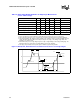
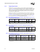
Table 29. BCLK/PICCLK Signal Quality Specifications for Simulation at the Processor Pins
(for the FC-PGA/FC-PGA2 Packages)
T# Parameter Min Nom Max Unit Figure Notes
V1: BCLK VIL 0.50 V 11
V1: PICCLK V
IL 0.70 V 11
V2: BCLK V
IH 2.00 V 11
V2: PICCLK V
IH 2.00 V 11
V3: V
IN Absolute Voltage Range –0.58 3.18 V 11
V4: BCLK Rising Edge Ringback 2.00 V 11 2
V4: PICCLK Rising Edge Ringback 2.00 V 11 2
V5: BCLK Falling Edge Ringback 0.50 V 11 2
V5: PICCLK Falling Edge Ringback 0.70 V 11 2
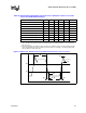
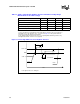
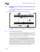
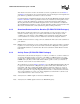
Figure 11. BCLK, TCK, PICCLK Generic Clock Waveform at the Processor Core Pins
V2
V1
V3
V3
T3
V5
V4
T6 T4 T5