
Guidelines


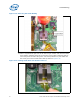
Table Of Contents
- 1 Introduction
- 2 Packaging Technology
- 3 Thermal Specifications
- 4 Thermal Simulation
- 5 Thermal Metrology
- 6 Reference Thermal Solution
- A Thermal Solution Component Suppliers
- B Mechanical Drawings
Intel® 3210 and 3200 Chipset Thermal/Mechanical Design Guide 21
Thermal Metrology
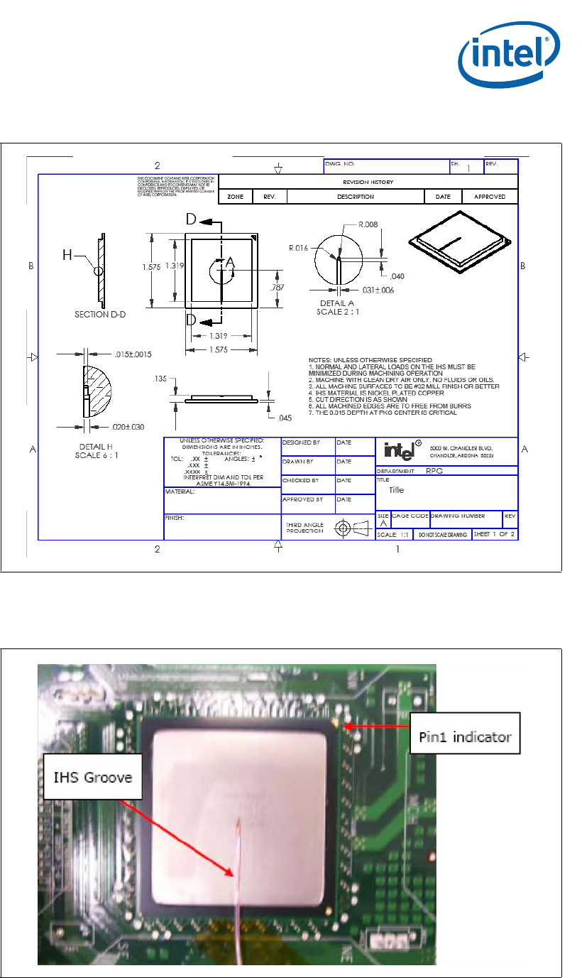
The orientation of the groove relative to the package pin 1 indicator (gold triangle in
one corner of the package) is shown in Figure 5-3 for the FCBGA7 chipset package IHS.
Figure 5-2. FCBGA7 Chipset Package Reference Groove Drawing
Figure 5-3. IHS Groove on the FCBGA7 Chipset Package on the Live Board