
Specifications

Board Architecture Intel® Remote Management Module 3
Revision 1.1
Intel order number E63789-002
10
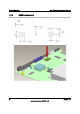
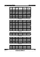
3. Board Architecture
The
Intel
®
RMM3
interfaces via
the
34-pin
header
to the Integrated Baseboard Management
Controller (BMC)
at
the
interfaces shown in the following block
diagram
.
Graphics
Controller
BMC & KVMS Subsystem
Super I/O Subsystem Graphics Subsystem
RTC &
General Purpose
TImers (3)
UART
(3)
I
2
C
(6)
Crypto
Accelerator
LPC to SPI
Flash Bridge
Watchdog
Timer
Real Time Clock
Interface
(external RTC)
LPC
Interface
To Host
RGB
Video
Output
PCIe x1
Interface
DDR-II
(up to
667MHz)
JTAG
Master
BMC Boot
Flash
USB
to Host
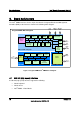
Integrated BMC Block Diagram
System
Wakeup
Control
KCS
BT &
Mailboxes
GPIOUART (3)
LPC
Interface
ARM926EJ-S
16K D & I
Cache
Interrupt
Controller
Fan Tach (12)
PWM (4)
ADC
Thermal
Ethernet
MAC with
RMII (2)
USB 1.1
&
USB 2.0
SPI Flash
BOOT & BKUP
DDR-II
16-bit
Memory
Controller
JTAG
Debug
Port
JTAG
Master
LPC
Master
LPC
Master
BMC Data
Flash
Figure 1: Integrated BMC/Intel
®
RMM3 block diagram
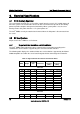
3.1
USB
2.0
(high-speed)
Interface
A
USB
2.0
(high-speed)
interface
supports
the
following:
Virtual
keyboard
Virtual
mouse
Intel
®
RMM3
-
Virtual
Media