
Specifications


Product Overview Intel® Remote Management Module 2
Revision 1.0
4
The
Intel
®
RMM2
connects
to
the
Intel
RMM
connector on the Intel server board.
The
Intel
RMM
connector
is
based on the
Advanced
Server
Management
Interface
(Intel
®
A
SMI)
specification.
The
Intel
®
RMM2
uses
a
sub-set
of
the
connector’s
pins.
It
connects
to
the
following
interfaces:
IPMB
DDC
DVO
RS232
FML
0 or FML
1
MII
USB
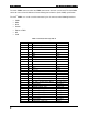
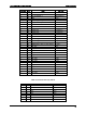
Table 1. Connector Pin-out, Side A
Pin Side A Pin Signal Intel® RMM
1 1 NC_RESERVED NO CONNECT
2 3 LPC_SYSRST_N SYSRST#
3 5 GND GND
4 7 NC RESERVED NO CONNECT
5 9 NC RESERVED NO CONNECT
6 11 GND GND
7 13 GND GND
8 15 USB1_P D+
9 17 USB1_N D-
10 19 GND GND
11 21 VCC 3.3V +3.3V
12 23 LAD0 LAD0
13 25 LAD1 LAD1
14 27 VCC 3.3V +3.3V
15 29 LCLK (33Mhz) LCLK (33Mhz)
16 31 VCC 3.3V +3.3V
17 33 NIC_FML1_MDA (Module Master) NIC_FML1_MDA
18 35 NIC_FML1_SDA (Module Master) NIC_FML1_SDA
19 37 NIC_FML1_MCL (Module Master) NIC_FML_MCL
20 39 NIC_FML1_SINTEX (Module Master) NIC_FML_SNTX
21 41 VCCa 3.3Aux +3.3V AUX
22 43 EMP/SOL_SERIAL_DSR RSER_DSR
23 45 EMP/SOL _SERIAL_RTS RSER_RTS
24 47 EMP/SOL_SERIAL_CTS RSER_CTS
25 49 EMP/SOL _SERIAL_DCD RSER_DCD
26 51 EMP/SOL _SERIAL_RI RSER_RI
27 53 EMP/SOL _SERIAL_TX RSER_TX
28 55 VCCa 3.3Aux +3.3V AUX
29 57 LCDCNTL[3] – PIXEL CLK VDCLK