
Specifications

Intel® Remote Management Module 2 Electrical Specifications
Revision 1.0
15
4.8
DVO
Video
and
DDC/EDID
Specifications
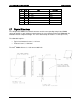
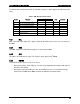
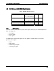
Table 5. DVO Bus DC Specifications
Parameter Condition Minimum Maximum
VIL- Low level input voltage Vout >/= VOH(Minimum)
or
Vout </= VOL(Maximum)
-0.3 V 1.0 V
VIH- High level input voltage Vout >/= VOH(Minimum)
or
Vout </= VOL(Maximum)
2.5 V 3.6 V
IIN- Input current Vin =0 or Vin = 3.3 V +/-10 uA
VOL- Low level output voltage VDD=3.1V, IOL=2mA 0.4 V
VOH- High level output voltage VDD=3.1V, IOH=-2mA 3.1 V
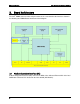
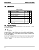
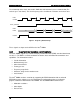
4.8.1 DVO Interface
The
DVO
interface
consists
of
three
groups
of
five
signals
that
represent
standard
digital
video
data.
The
groups
are:
Red
signals
Green
signals
Blue
signals
In
addition
to
the
15
video
data
signals,
the
ATI*
graphics
controller
on
the
server board
generates these
signals:
Clock
Data
enable
Horizontal
sync
signals
Vertical
sync
signals