
Specifications

Electrical Specifications Intel® Remote Management Module 2
Revision 1.0
14
4.5
IPMB
Specifications
The
Intel
®
RMM2
IPMB
bus
uses
3.3
V
signalling.
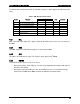
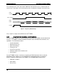
Table 4. I
2
C Interface
S
y
mbol Parameter
Minimum
Maximum Unit
Freq Operating frequency 400 KHz
Tbuf Bus free time between Stop and Start condition
(= Tcyc * (I2C_CLK_DIV+16))
4.7 us
thd:sta Hold time after (repeated) start condition. After this
period, the first clock is generated
(= Tcyc * (I2C_CLK_DIV-8))
4.0 us
tsu:sta Repeated Start condition setup time
(= Tcyc * (I2C_CLK_DIV+15))
4.0 us
tsu:sto Stop condition setup time
(= Tcyc * (I2C_CLK_DIV+15))
4.0 us
thd:data Data hold time from SCL 300 ns
tsu:data Data setup time to SCL 250 ns
Tf Clock/Data fall time into 100 pF capacitance and
4.7K ohm pullup.
300 ns
4.6
16550
UART
Interface
The
Intel
®
RMM2
has
one
16550
UART*
(RS232)
interface
for
serial
communication.
By
default,
the
RS232
port
is
disabled.
4.7 MII
Interface
The
Media
Independent
Interface
(MII)
is
an
Ethernet
(IEEE
802.3)
standard
for
communication
between
an
Ethernet
MAC
(Media
Access
Controller)
device
and
an
Ethernet
PHY
(Physical
layer
interface)
device.
The
MII
specification
defines
16
pins
per
port
for
data
and
control.
The
MII
allows
the
KIRA100* chip
on
the
Intel
®
RMM2
to
communicate
with
the
10/100
Ethernet
PHY
chip
on
the
Intel
®
GCM3 card.
The
Intel
®
GCM3
module
provides
the
RJ
45
connector
for
connection
to
the
LAN
via
a Category
5
network
cable.
The
RJ45
connector
on
the
Intel
®
GCM3
module
has
two
LEDs that
indicate
the
LAN
connector
state.
One
of
the
LEDs
indicates
link
activity
and
the
other indicates
the
LAN
speed
(10
or
100
Mb/S).