
Specifications

Intel® Remote Management Module 2 Electrical Specifications
Revision 1.0
13
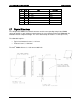
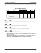
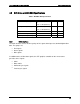
The
table
below
summarizes
the
DC
specifications
of
the
bus,
which
applies
for
both
master and
slave:
Table 3. FML Bus DC Specifications
Limits Symbol Parameter
Minimum Maximum
Units Comments
Vil Data, Clock input low voltage - 0.8 V
Vih Data, Clock input high voltage 2.0 - V
Vol Data, clock output low voltage - 0.4 V
Voh Data, clock output high voltage 2.4 - V
Vdd Nominal bus voltage 3.0 3.6 V 3.3V typical
Iih Input high current - 15 uA
Iil Input low current 15 - uA
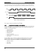
4.4.1
MCL
MCL
is
the
FML
clock
output.
This
signal
is
driven
by
the
FML
master.
In
this
case,
the
master is
the
BMC.
4.4.2
MDA
The
MDA
signal
is
the
FML
Data
Out
signal.
It
is
driven
by
the
BMC.
4.4.3
SDA
The
SDA
is
the
FML
Data
In
signal.
This
signal
is
driven
by
the
Intel
®
RMM2.
4.4.4
SINTEX
The
SINTEX
line
has
two
uses.
The
uses
are
as:
During
transactions
on
the
FML,
it
is
used
for
cycle
elongation
(to
introduce
wait states
in
the
active
transaction).
During
times
when
the
FML
bus
is
idle,
the
SINTEX
line
acts
as
an
attention
interrupt
from
the
Intel
®
RMM2
to
the
BMC,
to
initiate
an
FML
bus
Read
transaction.