
Specifications

Electrical Specifications Intel® Remote Management Module 2
Revision 1.0
12
4. Electrical Specifications
4.1
3.3
V
Auxiliary
Operation
The
server board
generates
the
3.3
V
auxiliary
supply
from
the
system’s
5
V
standby
power
rail
when
the
system
is
off.
Certain
other
devices
on
the
server
board
also
operate
on
5V standby
power
to
provide
complete
management
f
unctionality.
When
system
power
is
on,
the server
board
generates
this
power
from
the
3.3
V
system
power
rail.
The
Intel
®
RMM2
can
only
be
attached
and
removed
when
the
AC
power
is
disconnected
from
the
server.
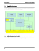
4.2
Power
System
The
Intel
®
RMM2
is
powered
from
the
system’s
standby
power
rail.
The
Intel RMM2
implements
its
own
power-on
reset
control, with a reset duration
sufficient
to
allow
all
clocks
and
PLL
circuits
to
stabilize
before
the
Intel RMM2
comes
out
of
reset.
There
is
a
one-second
delay
from
the
time
the
Intel
®
RMM2
comes
out
of
reset
to
its
first attempt
to
communicate
with
the
server board.
This
allows
the
server board
to
come
out
of its
own
power-on
reset.
The
cold
reset
signal
for
the
Intel RMM2
is
called
AC
present.
4.3 DC Specifications
All
pins
on
the
Intel
®
RMM
are
3.3
-
volt
tolerant, except for the
USB
signals,
which
are USB
compatible.
4.4
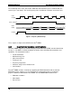
FML
Bus
Specifications
The
Fast
Management
Link
(FML)
is
an
Intel
standard
communication
bus
for
management
traffic.
It
handles
all
network
traffic
types
and
Internet
protocols.
The
FML
bus
is
comprised of
four
signals:
MCL
SINTEX
MDA
SDA