
Datasheet


Datasheet, Volume 1 49
Power Management
4.1.4 PCI Express* Link States
4.1.5 Direct Media Interface (DMI) States
4.1.6 Processor Graphics Controller States
4.1.7 Interface State Combinations
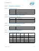
Table 4-4. PCI Express* Link States
State Description
L0 Full on – Active transfer state.
L0s First Active Power Management low power state – Low exit latency
L1 Lowest Active Power Management – Longer exit latency
L3 Lowest power state (power-off) – Longest exit latency
Table 4-5. Direct Media Interface (DMI) States
State Description
L0 Full on – Active transfer state
L0s First Active Power Management low power state – Low exit latency
L1 Lowest Active Power Management – Longer exit latency
L3 Lowest power state (power-off) – Longest exit latency
Table 4-6. Processor Graphics Controller States
State Description
D0 Full on, display active
D3 Cold Power-off
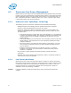
Table 4-7. G, S, and C State Combinations
Global (G)
State
Sleep
(S) State
Processor
Package
(C) State
Processor
State
System Clocks Description
G0 S0 C0 Full On On Full On
G0 S0 C1/C1E Auto-Halt On Auto-Halt
G0 S0 C3 Deep Sleep On Deep Sleep
G0 S0 C6
Deep Power
Down
On
Deep Power Down
G1 S3 Power off Off, except RTC Suspend to RAM
G1 S4 Power off Off, except RTC Suspend to Disk
G2 S5 Power off Off, except RTC Soft Off
G3 NA Power off Power off Hard off