
Datasheet


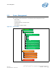

Power Management
Intel
®
Xeon
®
and Intel
®
Core™ Processors For Communications Infrastructure
May 2012 Datasheet - Volume 1 of 2
Document Number: 327405
-001 49
6.1.4 PCIe* Link States
6.1.5 DMI States
6.1.6 Interface State Combinations
6.2 Processor Core Power Management
While executing code, Enhanced Intel SpeedStep
®
Technology optimizes the
processor’s frequency and core voltage based on workload. Each frequency and voltage
operating point is defined by ACPI as a P-state. When the processor is not executing
code, it is idle. A low-power idle state is defined by ACPI as a C-state. In general, lower
power C-states have longer entry and exit latencies.
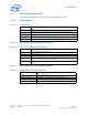
Table 6-4. PCIe* Link States
State Description
L0 Full on – Active transfer state.
L0s First Active Power Management low power state – Low exit latency.
L1 Lowest Active Power Management - Longer exit latency.
L3 Lowest power state (power-off) – Longest exit latency.
Table 6-5. DMI States
State Description
L0 Full on – Active transfer state.
L0s First Active Power Management low power state – Low exit latency.
L1 Lowest Active Power Management - Longer exit latency.
L3 Lowest power state (power-off) – Longest exit latency.
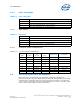
Table 6-6. G, S and C State Combinations
Global (G)
State
Sleep
(S) State
Processor
Core
(C) State
Processor
State
System Clocks Description
G0 S0 C0 Full On On Full On
G0 S0 C1/C1E Auto-Halt On Auto-Halt
G0 S0 C3 Deep Sleep On Deep Sleep
G0 S0 C6/C7
Deep Power-
down
On Deep Power Down
G1 S3 Power off Off, except RTC Suspend to RAM
G1 S4 Power off Off, except RTC Suspend to Disk
G2 S5 Power off Off, except RTC Soft Off
G3 NA Power off Power off Hard off