
Datasheet


Interfaces
Intel
®
Xeon
®
and Intel
®
Core™ Processors For Communications Infrastructure
Datasheet - Volume 1 of 2 May 2012
36 Document Number: 327405
-001
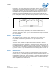
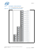
3.2.6 Lane Reversal on PCIe* Interface
The PCI Express* lanes can be reversed for ease of design and layout. Lane reversal is
done statically, which means that the BIOS needs to configure the reversal before the
relevant root port is enabled. For the x16 configuration, only one reversal option is
supported allowing either a straight or a rotated CPU on the motherboard. No other
combination of partial slot reversal is permitted. The reversal on x8 and x4
configurations are applied in a similar fashion.
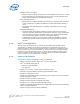
The normal or reversed configuration is determined by the configuration pins CFG[2]
for PCI express lanes on Port 1 and CFG[3] for lanes on Port 2. A value of '1' on these
inputs would indicate normal operation and a '0' would indicate reversed mode of
operation, as shown in Table 2.
Note: Performance estimates on early silicon have shown that bandwidth in x16 mode for
Gen 2 is approximately twice the bandwidth in x8 mode for read, write and read-write
transaction.
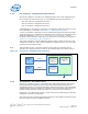
3.3 Direct Media Interface
Direct Media Interface (DMI) connects the processor and the PCH. Next generation
DMI2 is supported.
Note: Only DMI x4 configuration is supported.
3.3.1 DMI Error Flow
DMI can only generate SERR in response to errors, never SCI, SMI, MSI, PCI INT, or
GPE. Any DMI related SERR activity is associated with Device 0.
3.3.2 DMI Link Down
The DMI link going down is a fatal, unrecoverable error. If the DMI data link goes to
data link down, after the link was up, then the DMI link hangs the system by not
allowing the link to retrain to prevent data corruption. This link behavior is controlled
by the PCH.
Downstream transactions that had been successfully transmitted across the link prior
to the link going down may be processed as normal. No completions from downstream,
non-posted transactions are returned upstream over the DMI link after a link down
event.
3.4 Platform Environment Control Interface (PECI)
The PECI is a one-wire interface that provides a communication channel between a
PECI client (processor) and a PECI master. The processor implements a PECI interface
to:
Table 3-6. Hardware Straps for Normal/Reversed Operation of PCIe* Lanes
PCI-e Lanes Normal Reversed
Port 1 CFG [2] =1 CFG [2] =0
Port 2 CFG [3] =1 CFG [3] =0