
Datasheet

Electrical Specifications
Intel
®
Xeon
®
and Intel
®
Core™ Processors For Communications Infrastructure
Datasheet - Volume 1 of 2 May 2012
102 Document Number: 327405
-001
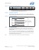
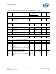
Table 9-14. Differential Clocks (SSC on)
SSC ON 1CLK 1 μs 0.1 s 0.1 s 1 μs1CLK
Signal
Name
-Jitter c-c
Abs
PerMin
-SSC Short
AvgMin
-ppm Long
AvgMin
Ideal DC
Target
+ppm
Long
AvgMax
+SSC
Short
AvgMax
+Jitter c-c
Abs
PerMax
Units
BCLK 9.849063 9.999063 10.02406 10.02506 10.02607 10.05120 10.20120 ns
Notes:
1. Ideal DC Target: This serves only as an ideal reference target (0 ppm) to use for calculating the rest of the period
measurement values
2. 0.1-second Measurement Window (frequency counter): Valuable measurement done using a frequency counter to
determine near DC average frequency (filtering out all jitter including SSC and cycle to cycle). This is used to determine
if the system has a frequency static offset caused usually by incorrect crystal, crystal loading or incorrect clock
configuration.
3. 1.0-μs Measurement Window (scope): This measurement is only used in conjunction with clock post processing software
(Jit3 Advanced for example) with “filters = LPF 3RD order 1-MHz pole” to filter out high frequency jitter (FM) and show
the underlying SSC profile. The numbers here bound the SSC min/ max excursions (SSC magnitude).
4. 1CLK - No Filter: Any 1 Period measured with a scope. Measured on a real time Oscilloscope using no filters, a simple
period measurement (or a Jit3 period measurement - more accurate), provides absolute Min/Max timing information.
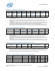
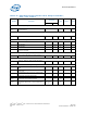
Table 9-15. Differential Clocks (SSC off)
SSC OFF 1CLK 0.1s 0.1s 1CLK
Signal Name
-Jitter c-c
AbsPerMin
-ppm
LongAvgMin
Ideal DC
target
+ppm
LongAvgMax
+Jitter c-c
AbsPerMax
Units
BCLK 9.849000 9.999000 10.00000 10.00100 10.15100 ns
Notes:
1. Ideal DC Target: This serves only as an ideal reference target (0ppm) to use for calculating the rest of the period
measurement values
2. 0.1-second Measurement Window (frequency counter): Valuable measurement done using a frequency counter to
determine near DC average frequency (filtering out all jitter including SSC and cycle to cycle). This is used to determine
if the system has a frequency static offset caused usually by incorrect crystal, crystal loading or incorrect clock
configuration.
3. 1CLK - No Filter: Any 1 Period measured with a scope. Measured on a real time Oscilloscope using no filters, a simple
period measurement (or a Jit3 period measurement - more accurate), provides absolute Min / Max timing information.
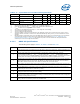
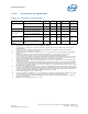
Table 9-16. Processor Clock Jitter Specifications (cycle-cycle)
Symbol
Frequency
(MHz)
Type
Source
(ps)
Destination Notes
BCLK
JIT_CC
100 Input Diff 150 processor/memory/PCI Express* 1
Notes:
1. On all jitter measurements care should be taken to set the zero crossing voltage (for rising edge) of the clock to be the
point where the edge rate is the fastest. Using a Math function = Average (Derivative (Ch1)) and set the averages to 64,
place the cursors where the slope is the highest on the rising edge - usually the lower half of the rising edge. This is
defined because Flip Chip components prevent probing at the end of the transmission line. This will result in a reflection
induced ledge in the middle of the rising edge and will significantly increase measured jitter.
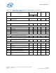
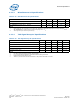
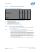
Table 9-17. System Reference Clock DC and AC Specifications
Symbol Parameter Signal Min Max Unit Meas Figure Notes
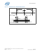
Slew_rise Rising Slew Rate Diff 1.5 4.0 V/ns Avg 9-3 2,3
Slew_fall Falling Slew Rate Diff 1.5 4.0 V/ns Avg 9-3 2,3
Slew_var Slew Rate Matching Single Ended 20 % Avg 9-4 1,9
V
SWING
Differential Output Swing Diff 300 mV RT 9-3 2